G3 Series EtherCAT
TM
Technical Manual
3-17
Subject to change without notice
www.asco.com/g3
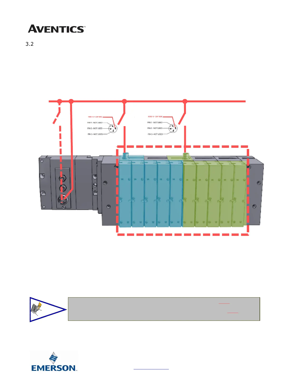
503 Series Zoned Power example
In the example shown below there are two Zoned Power Manifold blocks used. One is a "W" wiring option
and the other is a "V" wiring option. The first (5) stations of the manifold assembly get their power from
the M12 4 Pin connector at station one. The next (5) stations get their power from the M12 4 Pin
connector at station six. Each of these "Zones" can be individually switched of if the machine or process
requires. This example is considered a manifold with (2) Power Zones. The Main Power (7/8" MINI) cannot
be considered or used as a Power Zone; Switched Power (Solenoid/Output Power) MUST be present for
control to the solenoids.
S
NC
S-
NC
S-
NC
o
d
e
&
I
n
p
u
a
l
v
e
&
O
u
t
p
u
The 0 VDC reference for the +24 VDC applied to Pin 4 of the M12 connector MUST be the same
as the one used on G3/580/Terminal Strip/25 or 37 Pin Sub-D/19 or 26 Pin Round Connector.
If multiple 24 VDC power supplies are used the 0 VDC references of each supply MUST be
common.
 Loading...