G3 Series EtherCAT
TM
Technical Manual
4-20
Subject to change without notice
www.asco.com/g3
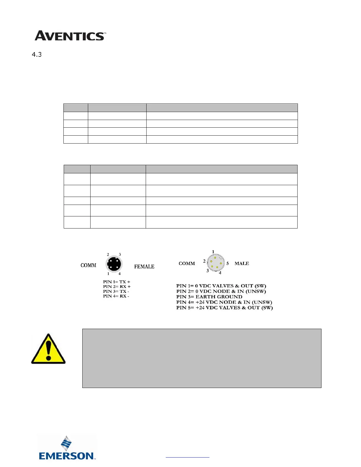
Connector Pin-Outs
Industry standard connectors are used for communication and auxiliary power.
The communication connectors are a D-coded keyway 4 pin female M12 connector.
The Power connector is a single keyway 5 pin male 7/8” MINI connector.
Communication Connector Pin-Out
Pin No. Function Description
1 TD+
Positive Transmit Line
2 RD+
Positive Receive Line
3 TD-
Negative Transmit Line
4 RD-
Negative Receive Line
Power Connector Pin-Out
Pin No. Function Description
1
0 VDC Common
(Valves and Outputs)
0 VDC Voltage used to power outputs
(valve coils and discrete outputs) SW
2
0 VDC Common
(Node and Inputs)
0 VDC Voltage used to power
discrete inputs and node electronics UNSW
4
+24 VDC
(Node and Inputs)
Voltage used to power
discrete inputs and node electronics UNSW
5
+24 VDC
(Valves and Outputs)
Voltage used to power outputs
(valve coils and discrete outputs) SW
• Power common (0 VDC) pins 1 and 2 are isolated from each other to allow separate
(isolated) power supply connection if required. However, they can be tied together if a
single common, non-isolated, application is preferred.
• The combined draw of the +24VDC Valves and Outputs and +24VDC Node and Inputs
pins cannot exceed 8 Amps, at any given moment in time.
• The Node and Inputs pin supplies power to the node electronics. This pin must be
powered at all times for communication node to be functional.
 Loading...