User Manual Section 5
GFK-2958L May 2021
Detailed Description of I/O Modules 207
In mode Pulse and Direction, channel CH0 A is used as the input and channel CH0 B as a
direction-determining input. In incremental mode, an incremental encoder with track A and
B can be connected. A status LED is assigned to each channel. The module electronics supply
the connected sensors with power from the input current path (IIN).
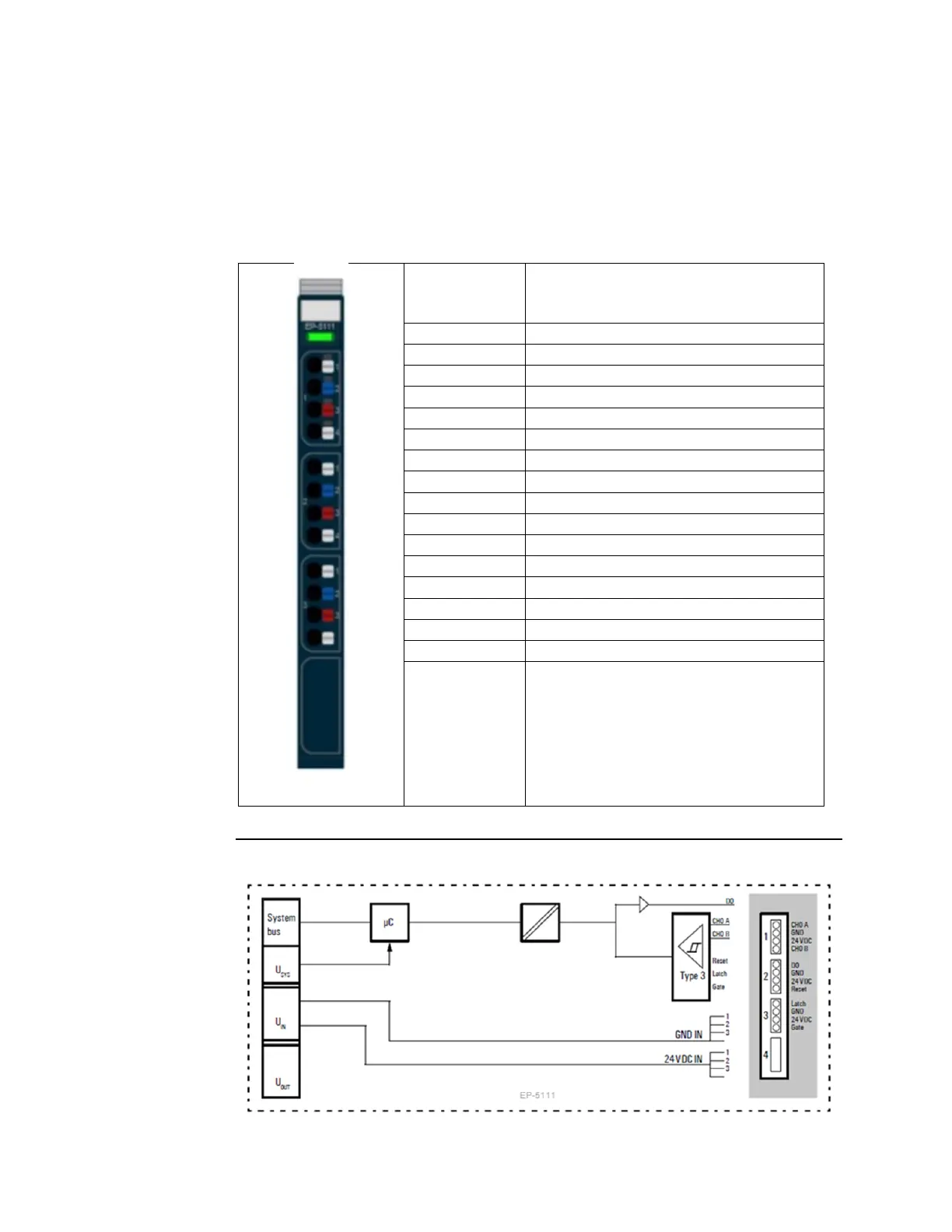
5.16.1 LED Indicators EP-5111
Green: Communication over the system bus
Red: Module System Fault or Diagnostic Fault
Yellow: A/pulse controlled
Yellow: B/direction controlled
Yellow: reset input controlled
Yellow: latch input controlled
Yellow: gate input (HW gate) controlled
For error messages refer to Section 12, LED Indicators and Troubleshooting
Figure 108: Block Diagram EP-5111

 Loading...


