User Manual Section 5
GFK-2958L May 2021
Detailed Description of I/O Modules 312
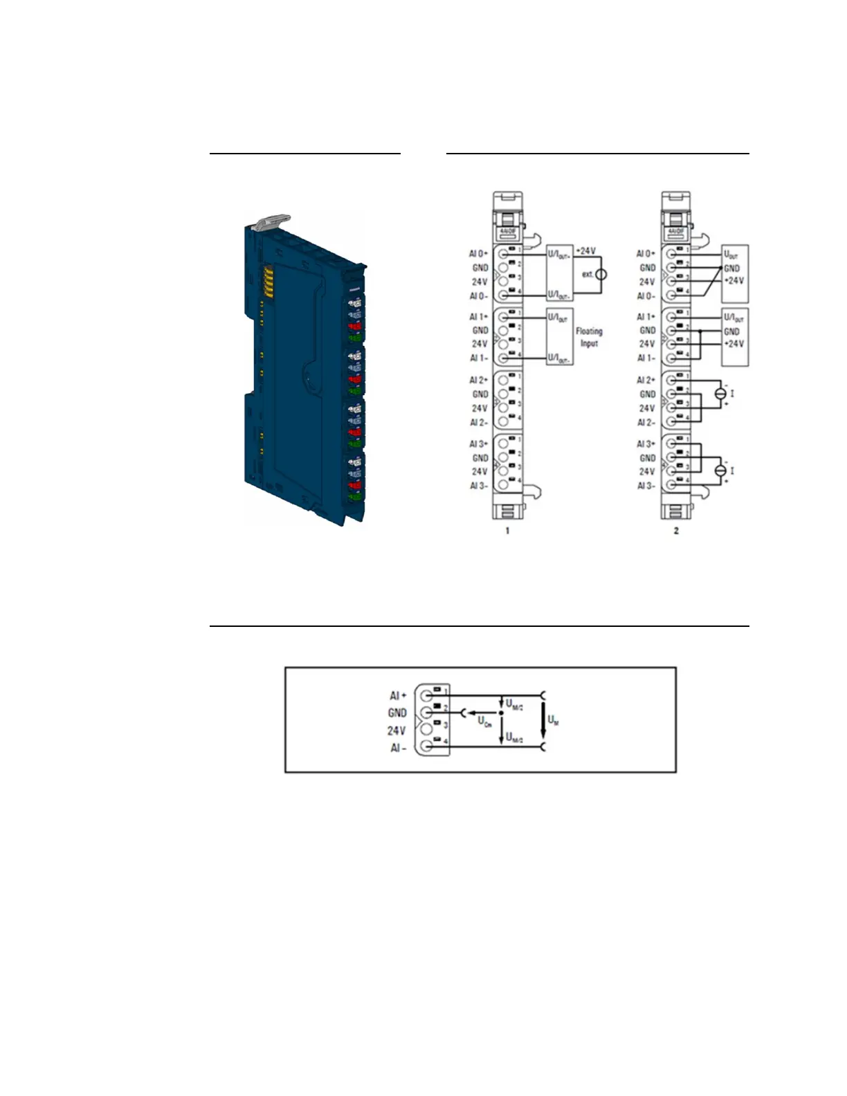
5.26 Analog Input Module EP-3664
Figure 176: Analog Input
Module EP-3664
Figure 177: Connection Diagram EP-3664
(Figure 178: For EP-3664, the 1= Standard, 2= Alternative option)
In the event that, you will realize the connection variant with an external sensor supply, pay
attention to the common mode range: Ucommon = -30V … +30V.
Figure 178: Definition of Common Mode (CM) EP-3664
The EP-3664 analog input module can record up to 4 analog sensors with ±10 V, ±5 V, 0-10
V, 0-5 V, 2-10 V, 1-5 V, 0-20 mA or 4-20 mA. The resolution is 16 bits per channel. Sensors
can be connected to each connector in a 2-wire, 3-wire or 4-wire connection. The
measurement range is defined using parameterization. Two status LED are assigned to each
channel. The module electronics supply the connected sensors with power from the input
current path (IIN).
Each sensor output is loadable with 500 mA and protected against overcurrent. The inputs
are protected against voltage surges and overcurrent. Voltages that exceed ±36 V against
GND may cause the destruction of the module. As a protection against overcurrent, the
module will cycle ON and OFF in high impedance mode.
The module provides individual channel diagnosis with channel related error messages.

 Loading...


