User Manual Section 4
GFK-2958L May 2021
Detailed Descriptions of the Fieldbus Network Adapters 68
4.2.1 LEDs
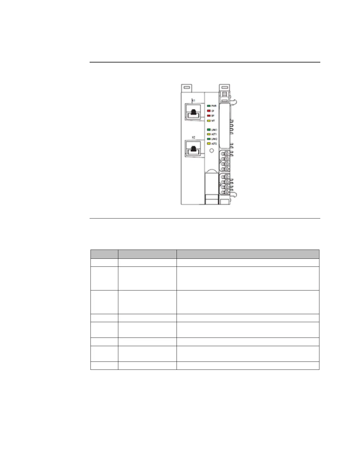
Figure 24:LED Status Indicators EPXPNS001/EPXPNS101
LED Status Indicators EPXPNS001/ EPXPNS101
Green: Supply voltage connected
Red: Configuration error, or error in the PROFINET Scanner,
or error in a module, or there is a new diagnostic report
Red flashing: Station in Force mode
Red: No connection to the fieldbus
Red flashing: Configuration error, no connection to the
control unit, or error in the parameter set
Yellow: Error on the system bus or the fieldbus
Green: Connection established between port 1 of the
PROFINET Scanner and another field device
Yellow flashing: Data being exchanged on port 1
Green: Connection established between port 2 of the
PROFINET Scanner and another field device
Yellow flashing: Data being exchanged on port 2

 Loading...


