User Manual Section 5
GFK-2958L May 2021
Detailed Description of I/O Modules 372
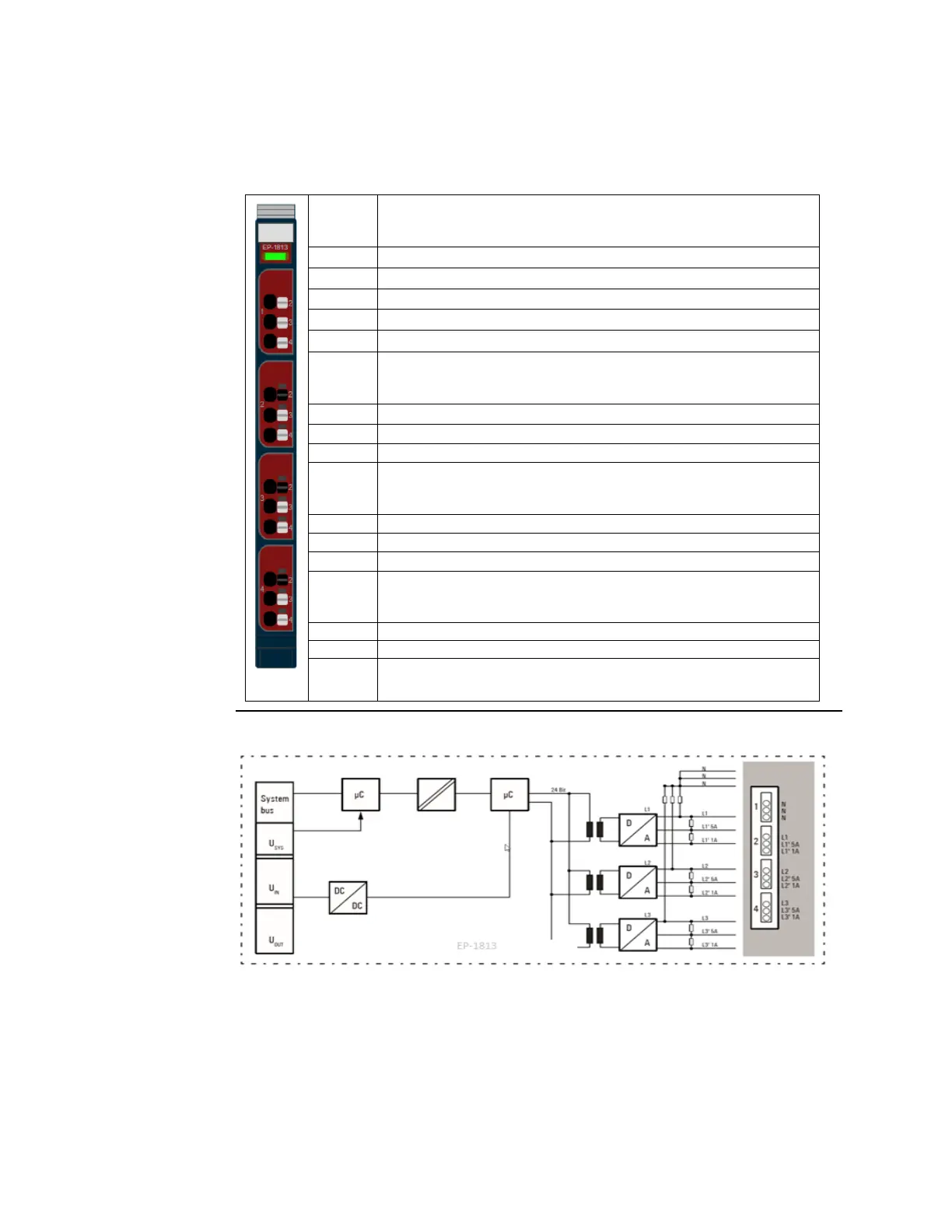
5.34.1 LED Indicators EP-1813
Green: Communication over the system bus
Red: Module System Fault or Diagnostic Fault (Collective error
diagnostics)
Yellow: Voltage >70 V at L1
Yellow flashing: Running light with 3.2 and 4.2 indicates the phase
sequence
Red: (parameterized) current alarm limit
1
exceeded
Red: (parameterized) voltage alarm limit
2
exceeded
Yellow: Voltage >70 V at L2
Yellow flashing: Running light with 2.2 and 4.2 indicates the phase
sequence
Red: (parameterized) current alarm limit
1
exceeded
Red: (parameterized) voltage alarm limit
2
exceeded
Red: Line break or range exceeded input 3
Yellow: Voltage >70 V at L3
Yellow flashing: Running light with 2.2 and 3.2 indicates the phase
sequence
Red: (parameterized) current alarm limit
1
exceeded
Red: (parameterized) voltage alarm limit
2
exceeded
1) Max. nominal input current 1 A bzw. 5 A
2) Max. nominal input voltage 300 V
Figure 207: Block Diagram EP-1813

 Loading...


