EasyManuals Logo
Home>Emerson>Controller>PACSystems RSTi-EP

Emerson PACSystems RSTi-EP User Manual

Emerson PACSystems RSTi-EP
539 pages
To Next Page IconTo Next Page
To Previous Page IconTo Previous Page
Page #345 background imageLoading...
Page #345 background image
User Manual Section 5
GFK-2958L May 2021
Detailed Description of I/O Modules 331
2-wire, 3-wire or 3-wire connection + FE (IDC). The measurement range is defined using
parameterization. A status LED is assigned to each channel. The module electronics supply
the connected sensors with power from the input current path (IIN).
The inputs are protected against voltage surges and overcurrent. Voltages that exceed ±30
V may cause the destruction of the module. The inputs are protected against overcurrent
by a self-resetting fuse.
The module provides individual channel diagnosis with channel related error messages.
Note: The high density plugs EP-8360 for EP-3468 needs to be ordered separately, as the
EP-3468 is not shipped with the HD plug unit.
5.29.1 LED Indicators EP-3468
Module Status
Green: Communication over the system bus
Red: Module System Fault or Diagnostic Fault
1.1
Red: channel error
2.1
Red: channel error
3.1
Red: channel error
4.1
Red: channel error
5.1
Red: channel error
6.1
Red: channel error
7.1
Red: channel error
8.1
Red: channel error
For error messages refer to Section 12, LED Indicators and Troubleshooting.
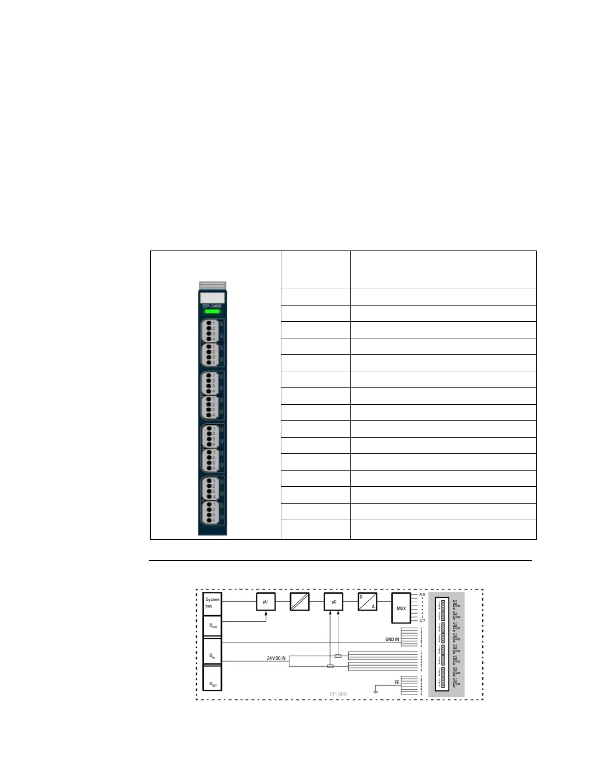
Figure 188: Block Diagram EP-3468

Table of Contents

Other manuals for Emerson PACSystems RSTi-EP

Questions and Answers:

Question and Answer IconNeed help?

Do you have a question about the Emerson PACSystems RSTi-EP and is the answer not in the manual?

Emerson PACSystems RSTi-EP Specifications

General IconGeneral
BrandEmerson
ModelPACSystems RSTi-EP
CategoryController
LanguageEnglish

Related product manuals