User Manual Section 8
GFK-2958L May 2021
Commissioning 439
Figure 283
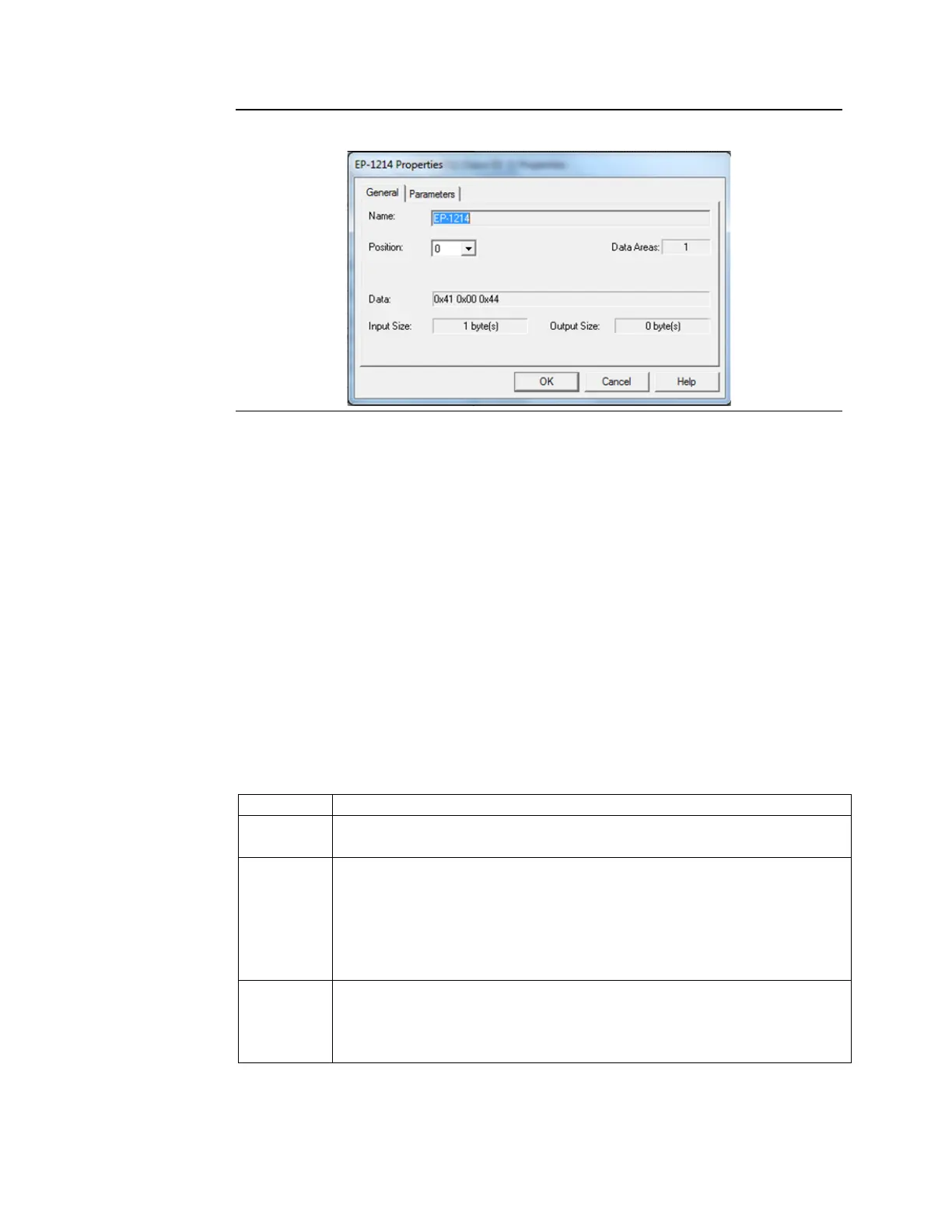
7. When finished adding modules, click OK. The modules display under the Slave node
in the Hardware Configuration.
Note: To add, remove, or change the order of modules associated with an existing slave,
right-click the Slave node in the Hardware Configuration and select Configure. The
Properties dialog box for the selected slave opens.
8.3.2 Configuring Module Data Areas
•
To configure module data areas: Right-click the Module node in the Hardware
Configuration, and select Configure. The Parameter Editor window for the module
displays.
The values for read-only parameters are supplied from the GSD text file that defines the
PROFIBUS module's characteristics. Most devices have one data area with inputs, outputs or
both. Some devices have multiple data areas that are shown as additional rows.
Data Area Parameters
This value is an index beginning at 1. Read-only.
Specifies whether the data is input or output as well as type, digital or analog. Value
can be Digital In, Analog In, Digital Out, or Analog Out.
Specifies the memory area that is used to map the data area. Regardless of the
reference type used, input areas are considered as consumed and cannot overlap,
while output areas are considered as produced and may overlap.
Allowable Ranges: %AI, %AQ, %I, %Q, %G, %R, %W, %T, %M.
If the number of bytes is odd, analog memories are not allowed and selections are
limited to: %I, %Q, %G, %M
Specifies the length of the reference. Includes the entire data area by default. If set to
0, the data area is not mapped.
For discrete memories, the allowable range is [0, 8, 16, …, X]
For analog memories, the allowable range is [0, 1, 2, …, X]

 Loading...


