User Manual Section 5
GFK-2958L May 2021
Detailed Description of I/O Modules 275
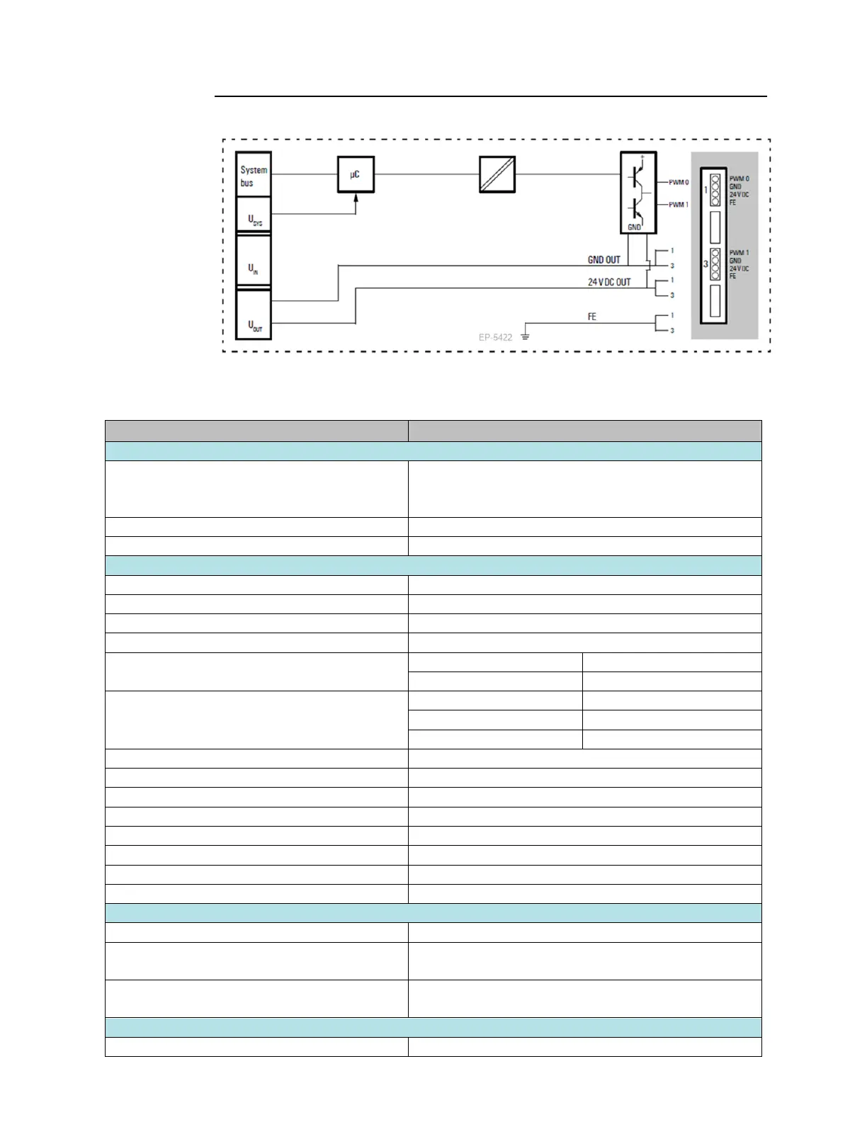
Figure 155: Block Diagram EP-5422
5.21.2 Specifications EP-5422
Process, parameter and diagnostic data depend on the
network adapter used (refer to Section 3.1, Order and
Arrangement of Modules).
RSTi-EP I/O communication bus
25
μ
s to 175ms (40 kHz to 6 Hz)
Resistive load (min. 47Ω)
2-wire, 3-wire, 3-wire + FE
max. 2 A per plug, total max. 4 A
0–100 % PN-switching or P-switching, adjustable
Response time of the protective circuit
Individual channel diagnosis
Current consumption from system current path
ISYS, typ.
Current consumption from output current path
IOUT

 Loading...


