䇭䇭㩷㩷㩷BB number㩷㪄㩷XBU number㩷㪄㩷Connector position䇭
䇭䇭䇭(BB00...BB15) - (XBU0...XBU1) - (0L,0R...2L,2R)
䇭䇭䇭XBU number㩷㪄㩷XBU number㩷㪄㩷Connector position
䇭䇭䇭(BB80...BB83) - (XBU0...XBU2) - (L0,R0...L7,R7)
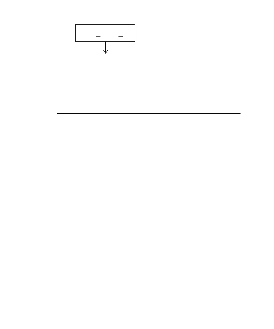
BB00
XBU0
2L
XB82
XBU2
L0
Note
-
The
connector
label
shows
both
the
cable
connection
destination
and
the
unit
connected
by
the
cable.
Figure
4-18
Connector
indication
example
of
a
crossbar
cable
4.3.3 Connecting
XSCF
cables
Cables
that
pass
between
racks
are
secured
to
expansion
rack
2.
Connect
cables
to
their
respective
ports
on
expansion
rack
1
through
the
empty
space
in
the
connecting
part
of
the
racks.
For
the
cable
routes,
see
Figure
4-19.
When
laying
the
cables,
use
the
supplied
hook-and-loop
fastener
strips
to
bundle
them
as
appropriate.
1.
Pass
the
XSCF
BB
control
cables
stored
in
expansion
rack
2
through
the
upper
side
of
the
connecting
part
of
the
racks
(B
in
Figure
4-14
).
2.
Connect
the
XSCF
BB
control
cables.
Connect
the
cables
such
that
the
port
indications
on
each
chassis
match
the
labels
on
the
cables.
Fujitsu
M10/SPARC
M10
Systems
Installation
Guide
・
July
2015158
 Loading...