8.2.2 Calling a Subroutine
A subroutine invoked in the program is using a CALL instruction. Up to 64 subroutine
block declarations and 64 CALL instructions are allowed for each block in the program.
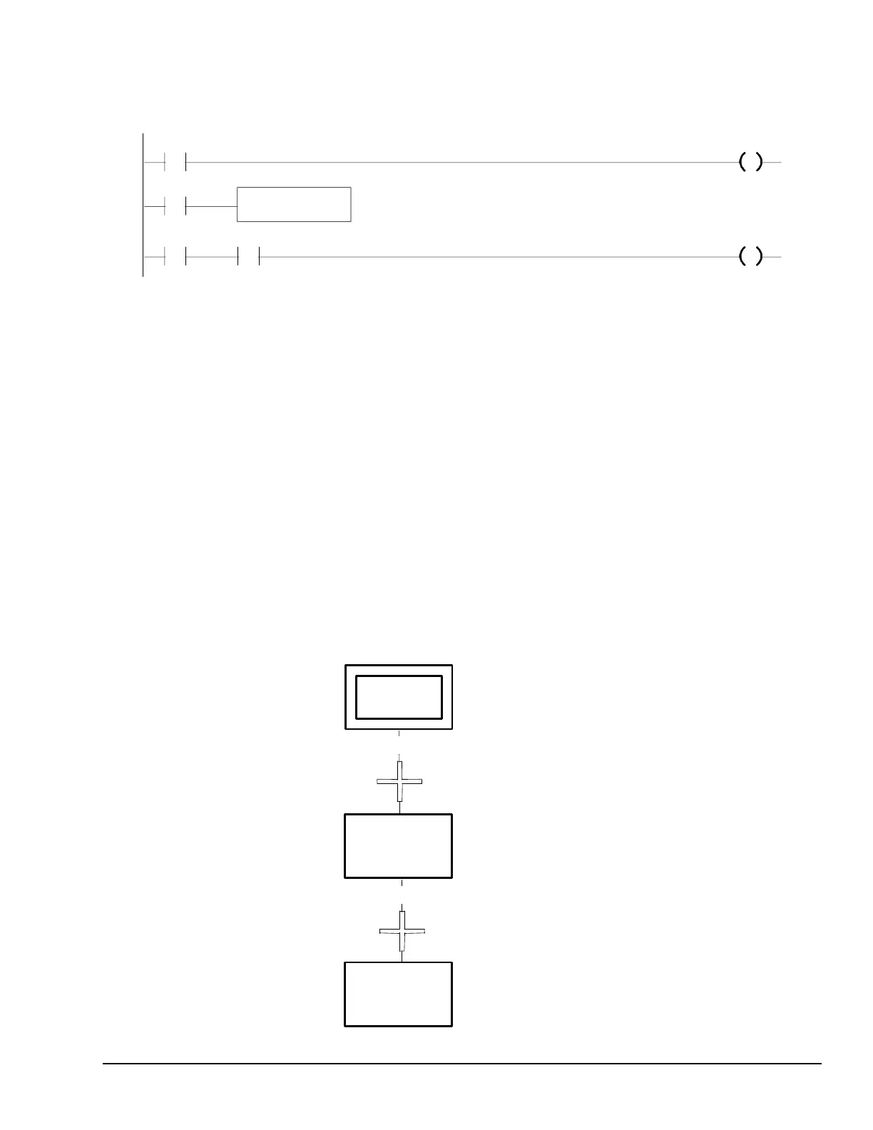
%I0004 %Q0001
%I0006
%I0003 %Q0010
CALL subroutine
%I0010
8.3 Program Languages
Programs can be created in Ladder Diagram or Instruction List format. The main program
or subroutines within the program can also be created in Sequential Function Chart
format. The PLC programming software can be used to create both types of logic.
8.3.1 Sequential Function Chart
Sequential Function Chart (SFC) is a graphic method of representing the functions of a
sequential automated system as a sequence of steps and transitions. Each step represents
commands or actions that are either active or inactive.
The flow of control passes from one step to the next through a conditional transition that
is either true (1) or false (0). If the transition condition is true (1), control passes from the
current step (which becomes inactive) to the next step, which then becomes active.
The logic associated with a step is executed when the step is active. This logic is
programmed in Ladder Diagram format. The transitions between steps are also
programmed as Ladder Diagram logic.
Transition 2
Transition 1
Elements of an Application Program GFK-1503E User Manual 105
For public disclosure

 Loading...


