5.2 Configuring Racks and Slots
Even though a VersaMax PLC does not have a module rack, both autoconfiguration and
software configuration use the traditional convention of racks and slots to identify module
locations in the system. Each logical rack consists of the CPU or an Expansion Receiver
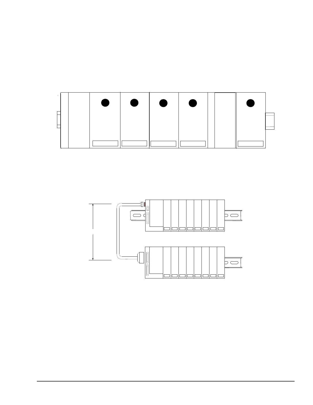
module plus up to 8 additional I/O and option modules mounted on the same DIN rail.
Each I/O or option module occupies a slot. The module next to the CPU or Expansion
Receiver module is in slot 1. Booster power supplies do not count as occupying slots.
The main rack is rack 0. Additional racks are numbered 1 to 7.
In a system that uses just one expansion rack which is attached to the expansion bus by a
non-isolated Expansion Receiver Module (IC200ERM002), the expansion rack must be
configured as rack 1.
VersaMax PLC Station Main Rack
Configuration GFK-1503E User Manual 71
For public disclosure

 Loading...


