4.2 Installing an Expansion Transmitter Module
If the VersaMax PLC will have more than one expansion rack or one expansion rack that
uses an Isolated Expansion Receiver Module (IC200ERM001) as its interface to the
expansion bus, an Expansion Transmitter Module must be installed to the left of the CPU.
The Expansion Transmitter Module must be installed on the same section of DIN rail as
the rest of the modules in the main rack (rack 0).
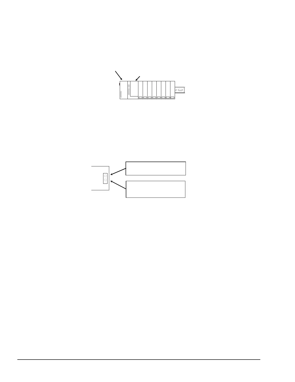
VersaMax PLC Main Rack (0)
Expansion Transmitter Module
1. Make sure rack power is off.
2. Attach the Expansion Transmitter to DIN rail to the left of the CPU position.
3. Install the CPU. Connect the modules and press them together until the connectors
are mated.
4. After completing any additional system installation steps, apply power and observe
the module LEDs.
EXP TX
On indicates presence of 5VDC power.
Off indicates no 5VDC power.
Blinking or On indicates active
communications on expansion bus.
Off indicates no communications.
4.2.1 Removing an Expansion Transmitter Module
1. Make sure rack power is off.
2. Slide module on DIN rail away from the CPU in the main rack.
3. Using a small screwdriver, pull down on the tab on the bottom of the module and lift
the module off the DIN rail.
54 GFK-1503E VersaMax PLC User Manual
For public disclosure

 Loading...


