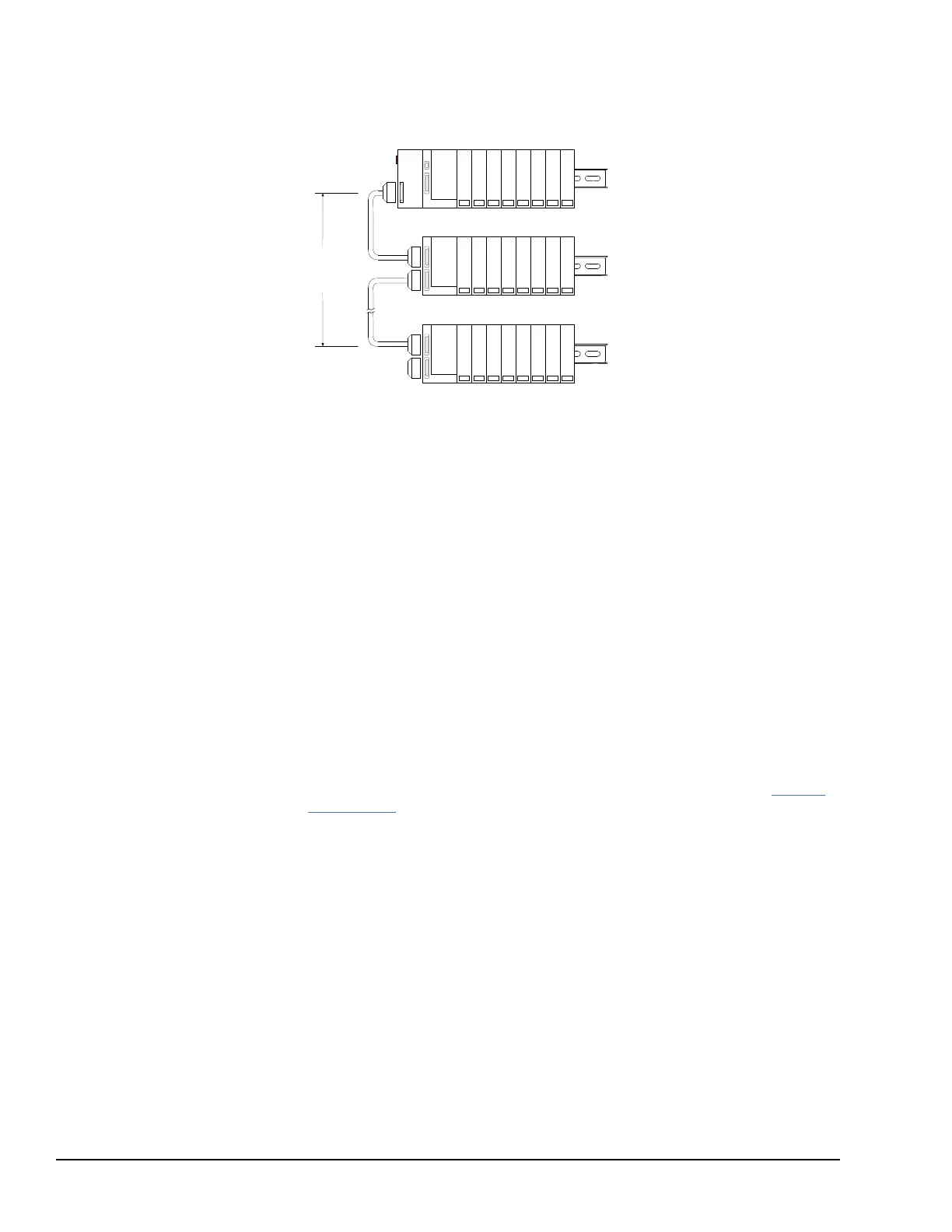
In a system with an Expansion Transmitter Module (IC200BTM001) and up to seven
expansion racks, each with an Isolated Expansion Receiver Module (IC200ERM001 or
IC200ERM002), the additional racks are configured as rack 1 through rack 7.
VersaMax PLC Main Rack (0)
5.3 Software Configuration
The configuration software makes it possible to create a customized configuration for the
VersaMax PLC system. For CPUE05, it is also used to configure Ethernet Global Data.
When you enter Hardware Configuration for VersaMax equipment folders, the default
view is the Rack (Main). A new configuration already includes a default power supply
(PWR001) and CPU (CPU001). Both can easily be changed to match the actual hardware
in the PLC system.
To configure the PLC, you will:
• Configure the rack type (non-expanded, single-ended expanded, or multi-rack
expanded).
• Configure the power supply type and any booster power supplies and carriers. (Note
that CPU005 and CPUE05 both require an expanded 3.3V supply.)
• Configure the CPU. This includes changing the CPU type if necessary, and assigning
its parameters as described in this chapter.
• Configure the parameters of the CPU serial ports, as explained in this chapter.
• For CPUE05, configure its Ethernet parameters, as explained in chapter 6, Ethernet
Configuration.
• Configure the expansion modules if the system has expansion racks.
• Add module carriers and define wiring assignments.
• Place modules on carriers and select their parameters. Configurable parameters of I/O
modules are described in the VersaMax Modules, Power Supplies, and Carriers User
Manual (GFK-1504).
• Save the configuration file so that it can be stored to the PLC.
Step-by-step instructions for using the configuration software are provided in the
VersaPro Software User Manual (GFK-1670). Additional information is available in the
online help.
5.3.1 Configuring CPU and Expansion Parameters
The table below lists configurable parameters for VersaMax PLC CPUs, and for
expansion racks.
72 GFK-1503E VersaMax PLC User Manual
For public disclosure

 Loading...


