1.3.1 Available Power Supplies and Carrier
The following VersaMax power supplies and carrier are available:
24VDC Power Supply IC200PWR001
24VDC Expanded 3.3V Power Supply IC200PWR002
120/240VAC Power Supply IC200PWR101
120/240VAC Expanded 3.3V Power Supply IC200PWR102
12VDC Power Supply IC200PWR201
12VDC Expanded 3.3V Power Supply IC200PWR202
Power Supply Booster Carrier IC200PWB001
Power supplies are described in the VersaMax Modules, Power Supplies, and Carriers
User Manual (GFK-1504).
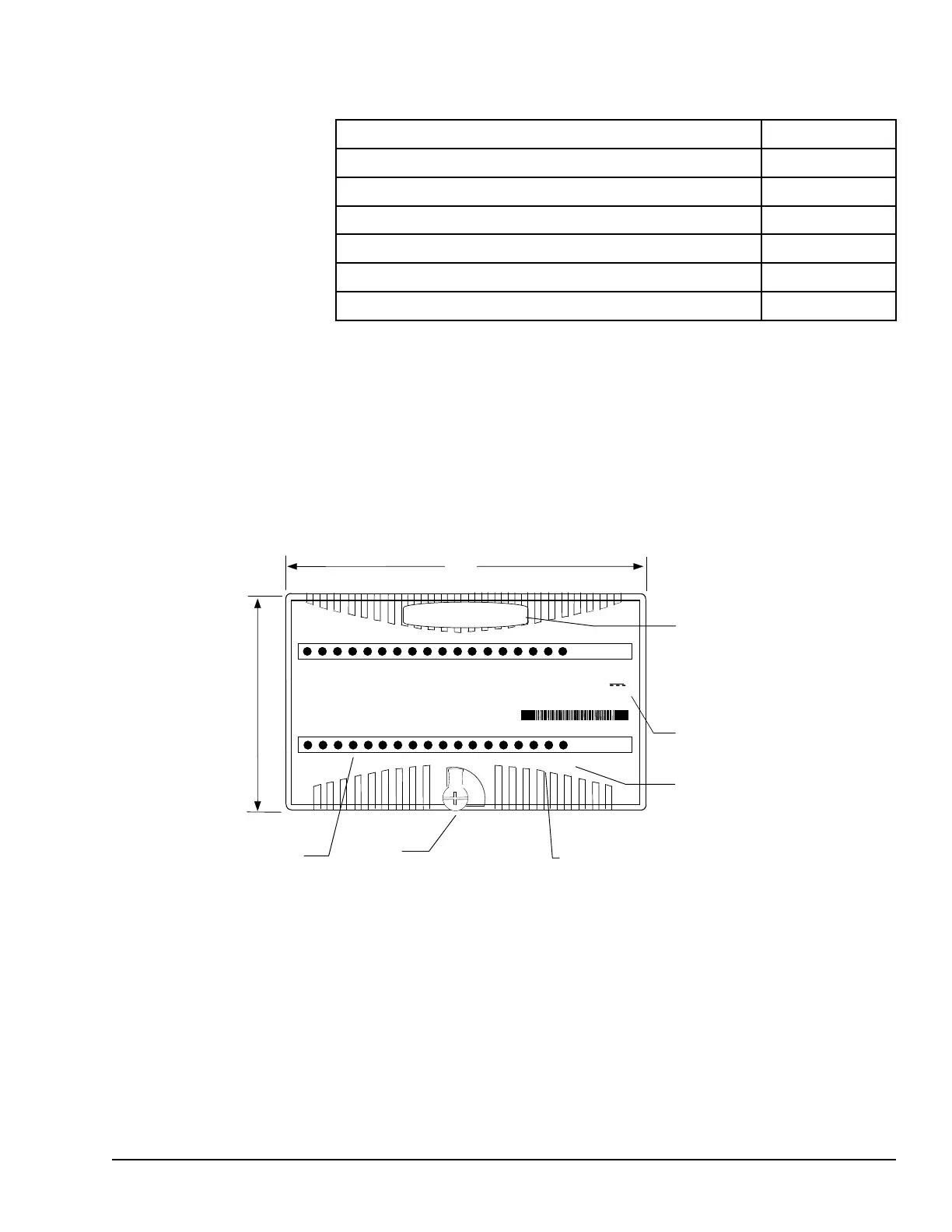
1.4 I/O Modules
VersaMax I/O and option modules are approximately 110mm (4.33in) by 66.8mm
(2.63in) in size. Modules can be mounted either horizontally or vertically on several types
of available I/O Carriers. Modules are 50mm (1.956 in) in depth, not including the height
of the carrier or the mating connectors.
Individual Point LEDS on Discrete Modules
Fie
ld Power LED indicates presence of power from external supply
OK LED indicates presence of power from VersaMax power supply
Color code:
Red: AC
Blue: DC
Gold: Mixed
Gray: Analog/other
VersaMax I/O modules are described in the VersaMax Modules, Power Supplies, and
Carriers User’s Manual (GFK-1504).
Introduction GFK-1503E User Manual 21
For public disclosure

 Loading...


