9.1 Data Memory References
The PLC stores program data in both bit memory and word memory. Both bit memory
and word memory are divided into different types with specific characteristics.
By convention, each type is normally used for a specific type of data, as explained below.
However, there is great flexibility in actual memory assignment.
Individual memory locations are indexed using alphanumeric identifiers called references.
The reference’s letter prefix identifies the memory area. The numerical value is the offset
within that memory area.
9.1.1 Word Memory References
Each word memory address (reference) is on a 16-bit word boundary. The PLC uses three
types of references for data stored in word memory.
%AI Normally used for analog inputs.
%AQ Normally used for analog outputs.
%R Registers are normally used to store program data in word format.
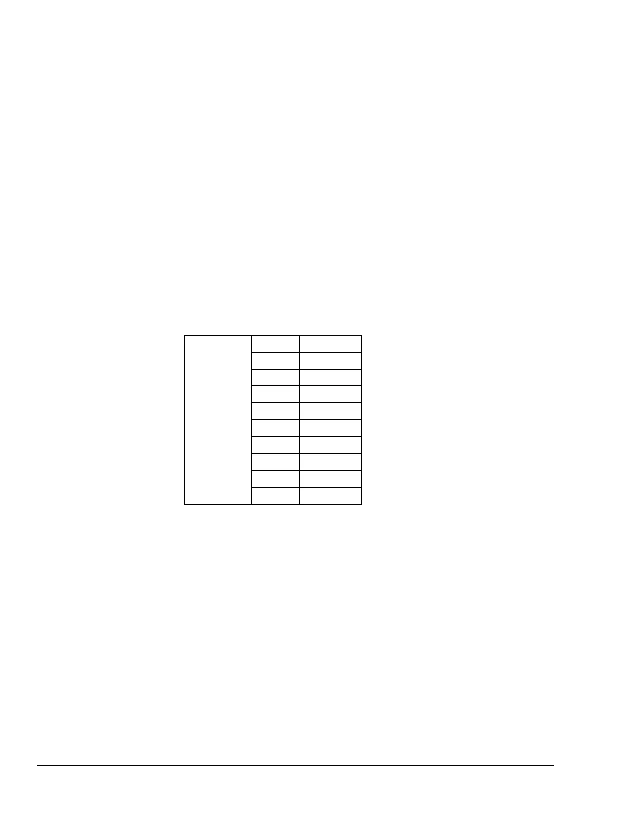
Word memory is represented below. The example below shows ten addresses. Each has
16 bits that together contain one value. The PLC cannot access individual bits in word
memory.
addresses 1 12467
2 12004
3 231
4 359
5 14
6 882
7 24
8 771
9 735
10 0
114 GFK-1503E VersaMax PLC User Manual
For public disclosure