EasyManua.ls Logo

GE VersaMax PLC User Manual

GE VersaMax PLC
318 pages
To Next Page IconTo Next Page
To Previous Page IconTo Previous Page
Page #205 background imageLoading...
Page #205 background image
11.8 SVCREQ 7: Read or Change the Time-of-Day Clock
Use SVCREQ 7 to read or change the time of day clock in the PLC. The data can be
either BCD or ASCII. Either 2-digit-year or 4-digit-year format is available. The function
is successful unless some number other than 0 (read) or 1 (change) is entered for the
requested operation, or an invalid data format is specified, or data is provided in an
unexpected format.
11.8.1 Parameter Block Format for SVCREQ 7
For the date/time functions, the length of the parameter block depends on the data format.
The data block is either BCD or ASCII. BCD format requires 6 words; packed ASCII
requires 12 words (13 words for 4-digit year). For both data types:
• Hours are stored in 24-hour format.
• Day of the week is a numeric value from 1 (Sunday) to 7 (Saturday).
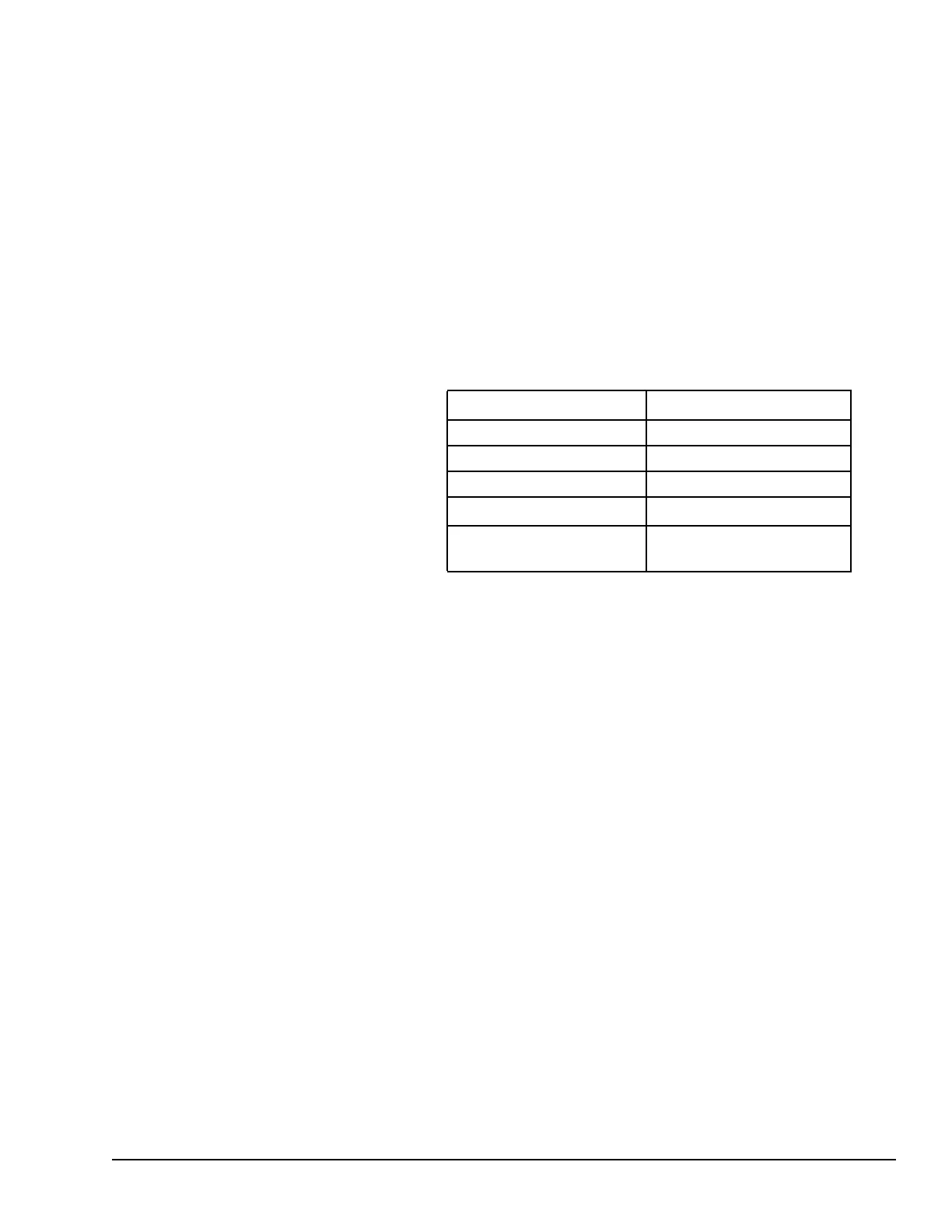
2-Digit Year Format 4-Digit Year Format
address
0 = read time and date 0 = read time and date
1 = set time and date 1 = set time and date
address + 1
1 = BCD format 81h = BCD format
3 = packed ASCII format 83h = packed ASCII format
address + 2 to
end
data data
Words 3 to the end of the parameter block contain output data returned by a read function,
or new data being supplied by a change function. In both cases, format of these data
words is the same. When reading the date and time, words (address + 2) to the end of the
parameter block are ignored on input.
The Service Request Function GFK-1503E User Manual 205
For public disclosure

Table of Contents

Questions and Answers:

GE VersaMax PLC Specifications

General IconGeneral
ModelVersaMax
TypeProgrammable Logic Controller (PLC)
I/O PointsVaries by configuration
Communication ProtocolsEthernet, Profibus, Modbus, Serial
Communication PortsRS-232, RS-485, Ethernet
Programming LanguagesLadder Logic, Function Block Diagram, Structured Text
Programming SoftwareProficy Machine Edition
Power Supply24V DC or 100-240V AC
CertificationsUL, CE, cUL

Summary

Document Updates

Related Documents

Acronyms and Abbreviations

Safety Symbol Legend

Contact Information

1 Introduction

1.1 The VersaMax Family of Products

Introduces the VersaMax product line, its features, and applications.

1.2 CPU Modules for VersaMax PLCs

Details the different CPU modules available for VersaMax PLCs and their specifications.

1.3 Power Supplies

Describes the power supply options and requirements for VersaMax systems.

1.4 I/O Modules

Lists and describes the various Input/Output (I/O) modules available for VersaMax PLCs.

1.5 Carriers

Explains the different types of carriers used for mounting VersaMax modules.

1.6 Expansion Modules

Details the types and usage of expansion modules for VersaMax I/O systems.

1.7 Communications Modules

Lists and describes the communication modules that enhance VersaMax system flexibility.

2 CPU Module Datasheets: CPU001, CPU002, CPU005

2.1 Features

Outlines the key features and capabilities of the CPU001, CPU002, and CPU005 modules.

2.2 Module Specifications

Provides detailed technical specifications for the CPU001, CPU002, and CPU005 modules.

2.3 VersaMax General Product Specifications

Covers general environmental and EMC specifications applicable to VersaMax products.

2.4 Serial Ports

Describes the serial port configurations, capabilities, and cable lengths for CPU modules.

2.5 Mode Switch

Explains the function and operation of the CPU module's mode switch.

2.6 CPU LEDs

Details the meaning and function of the various LEDs on the CPU module.

2.7 Configurable Memory

Describes the memory allocation for CPU modules and its configurable aspects.

3 CPU Module Datasheet: CPUE05

3.1 Features

Lists the features of the CPUE05 CPU module, including its Ethernet interface.

3.2 Module Specifications

Provides detailed technical specifications for the CPUE05 CPU module.

3.3 VersaMax General Product Specifications

Covers general environmental and EMC specifications applicable to VersaMax products.

3.4 Serial Ports

Details the serial port configurations for the CPUE05, including port usage and protocols.

3.5 Ethernet LAN Port

Describes the Ethernet LAN port capabilities, connection standards, and auto-selection.

3.6 Mode Switch

Explains the function and operation of the CPUE05 module's mode switch.

3.7 CPU LEDs

Details the meaning of the LEDs on the CPUE05 module indicating status and activity.

3.8 Ethernet Restart Pushbutton

Explains the functions of the Ethernet Restart pushbutton on the CPUE05 module.

3.9 Ethernet LEDs

Describes the status and activity indicated by the Ethernet interface LEDs.

3.10 Configurable Memory

Details the configurable user memory for the CPUE05 module and its allocation.

3.11 Ethernet Interface Overview

Provides an overview of the CPUE05's Ethernet interface capabilities and features.

4 Installation

4.1 Mounting Instructions

Provides guidelines for mounting VersaMax modules and carriers on DIN rails or panels.

4.2 Installation of Expansion Transmitter Module

Details the procedure for installing an Expansion Transmitter Module.

4.3 Installing an Expansion Receiver Module

Explains how to install an Expansion Receiver Module into an expansion rack.

4.4 Installing Power Supply Modules

Covers the installation process for Power Supply modules onto CPUs, Expansion Receivers, or carriers.

4.5 Installing Additional Modules

Describes how to add I/O and option modules to a VersaMax rack.

4.6 Activating or Replacing the Backup Battery

Explains how to activate or replace the backup battery for the CPU module.

4.7 Serial Port Connections

Details serial port connections, including cable lengths and available pre-assembled cables.

4.8 Ethernet Connection for CPUE05

Provides instructions for connecting the CPUE05 module to a 10BaseT Ethernet network.

4.9 CE Mark Installation Requirements

Outlines requirements for surge, ESD, and FTB protection for CE Mark compliance.

5 Configuration

5.1 Using Autoconfiguration or Programmer Configuration

Explains the two methods for configuring VersaMax PLCs: autoconfiguration and programmer configuration.

5.2 Configuring Racks and Slots

Describes the convention of racks and slots used for module identification in VersaMax systems.

5.3 Software Configuration

Details the process of creating and applying a customized configuration using software.

5.4 Autoconfiguration

Explains how the CPU automatically generates a configuration based on installed modules.

6 Ethernet Configuration

6.1 Ethernet Configuration Overview

Provides an overview of the configuration steps for the VersaMax Ethernet interface.

6.2 Configuring the Ethernet Interface

Details the essential Ethernet interface parameters like IP address, subnet mask, and gateway.

6.3 Configuring Ethernet Global Data

Explains how to configure Ethernet Global Data exchanges between devices.

6.4 Configuring a Global Data Exchange for a Producer

Guides on configuring Ethernet Global Data exchanges from a producer's perspective.

6.5 Configuring a Global Data Exchange for a Consumer

Guides on configuring Ethernet Global Data exchanges for consumers, including selective consumption.

6.6 Configuring Advanced User Parameters

Covers the configuration of advanced operating parameters for the Ethernet interface.

7 CPU Operation

7.1 Parts of the CPU Sweep

Breaks down the sequence of operations performed by the CPU during a sweep cycle.

7.2 Standard CPU Sweep Operation

Describes the normal operating mode of the PLC CPU and its sweep execution.

7.3 CPU Stop Modes

Explains the different CPU stop modes: I/O Disabled and I/O Enabled.

7.5 Controlling the Execution of a Program

Details functions used to control program execution flow, like CALL, END, and JUMP.

7.6 Run/Stop Mode Switch Operation

Explains how the Run/Stop mode switch affects CPU operation and memory protection.

7.7 Privilege Levels and Passwords

Covers password protection and privilege levels for accessing PLC features.

8 Elements of an Application Program

8.1 Structure of an Application Program

Describes the fundamental structure of an application program within the PLC.

8.2 Subroutines

Explains the concept of subroutines and how they simplify programming.

8.3 Program Languages

Introduces the program languages supported, including Ladder Diagram and SFC.

8.4 The Instruction Set

Provides a reference to the various instructions and functions available in the PLC's instruction set.

9 Program Data

9.1 Data Memory References

Explains how data is stored and referenced in the PLC's memory.

9.2 Retentiveness of Data

Describes which data types are retentive and how their states are preserved.

9.3 System Status References

Details the system status references (%S, %SA, %SB, %SC) and their definitions.

9.4 How Program Functions Handle Numerical Data

Explains how program functions handle numerical data types like REAL, INT, and DINT.

9.5 Time-tick Contacts

Describes time-tick contacts used for providing regular pulses in program functions.

10 Instruction Set Reference

10.1 Bit Operation Functions

Covers functions for manipulating bits, including logical operations and shifts.

10.2 Control Functions

Details functions that control program execution, such as CALL, END, and MCR.

10.3 Data Move Functions

Explains functions used for moving data between different memory locations.

10.4 Data Type Conversion Functions

Describes functions for converting data between different numerical types.

10.5 Math and Numerical Functions

Covers mathematical and numerical operations like add, subtract, trig, and logs.

10.6 Relational Functions

Explains functions for comparing numbers and checking values against ranges.

10.7 Relay Functions

Details the basic relay functions, including contacts and coils for logic control.

10.8 Table Functions

Covers functions for array manipulation, including copying and searching.

10.9 Timer and Counter Functions

Describes timer and counter functions used for timing and counting operations in programs.

11 The Service Request Function

11.1 SVCREQ Function Numbers

Lists the function numbers and descriptions for various Service Request (SVCREQ) operations.

11.2 Format of the SVCREQ Function

Explains the general format and parameters for using SVCREQ functions.

11.3 SVCREQ 1: Change/Read Constant Sweep Timer

Details how to change or read the Constant Sweep Timer settings using SVCREQ 1.

11.4 SVCREQ 2: Read Window Times

Explains how to read the times for programmer and system communications windows using SVCREQ 2.

11.5 SVCREQ 3: Change Programmer Communications Window Mode

Describes how to change the mode of the programmer communications window using SVCREQ 3.

11.6 SVCREQ 4: Change System Communications Window Mode

Explains how to change the system communications window mode using SVCREQ 4.

11.7 Change/Read Number of Words to Checksum

Details how to read or change the number of words for program checksumming using SVCREQ 6.

11.8 SVCREQ 7: Read or Change the Time-of-Day Clock

Covers reading or changing the PLC's time-of-day clock using SVCREQ 7.

11.9 SVCREQ 8: Reset Watchdog Timer

Explains how to reset the watchdog timer during a sweep using SVCREQ 8.

11.10 SVCREQ 9: Read Sweep Time from Beginning of Sweep

Describes how to read the elapsed time since the sweep start using SVCREQ 9.

11.11 SVCREQ 10: Read Folder Name

Explains how to read the name of the currently executing folder using SVCREQ 10.

11.12 SVCREQ 11: Read PLC ID

Details how to read the PLC ID of the executing PLC using SVCREQ 11.

11.13 SVCREQ 13: Shut Down (Stop) PLC

Explains how to stop the PLC at the end of the next sweep using SVCREQ 13.

11.14 SVCREQ 14: Clear Fault

Describes how to clear the PLC fault table or I/O fault table using SVCREQ 14.

11.15 SVCREQ 15: Read Last-Logged Fault Table Entry

Explains how to read the last logged entry from the fault tables using SVCREQ 15.

11.16 SVCREQ 16: Read Elapsed Time Clock

Details how to read the system's elapsed time clock using SVCREQ 16.

11.17 SVCREQ 18: Read I/O Override Status

Explains how to check for I/O overrides in the CPU's %I and %Q memories using SVCREQ 18.

11.18 SVCREQ 23: Read Master Checksum

Covers reading master checksums of the application program and configuration using SVCREQ 23.

11.19 SVCREQ 24: Reset Ethernet Daughter Board

Explains how to reset the Ethernet daughterboard from ladder logic using SVCREQ 24.

11.20 SVCREQ 26/30: Interrogate I/O

Details how to check installed modules against software configuration using SVCREQ 26/30.

11.21 SVCREQ 29: Read Elapsed Power Down Time

Explains how to read the elapsed time between power-down and power-up using SVCREQ 29.

12 Serial I/O / SNP / RTU Protocols

12.1 Format of the Communication Request Function

Explains the format and parameters of the Communication Request (COMMREQ) function.

12.2 Configuring Serial Ports Using the COMMREQ Function

Provides tables for command block values required for setting up Serial Ports using COMMREQ.

12.3 Calling Serial I/O COMMREQs from the PLC Sweep

Discusses how Serial I/O COMMREQs are called from the PLC sweep and their compatibility.

12.4 Serial I/O COMMREQ Commands

Lists and describes various Serial I/O COMMREQ commands for port management.

13 Ethernet Communications

13.1 Overview of the Ethernet Interface

Provides an overview of the Ethernet interface capabilities for VersaMax CPU model IC200CPUE05.

13.2 IP Addressing

Explains IP address structure, classes, and formats used in Ethernet networks.

13.3 Routers

Describes the role of routers in connecting networks and facilitating communication.

13.4 Ethernet Global Data

Details Ethernet Global Data (EGD) for efficient data transfer between devices.

13.5 Diagnostic Tools

Lists tools and methods for diagnosing Ethernet operation and EGD problems.

13.6 Troubleshooting Common Ethernet Difficulties

Provides solutions for common Ethernet errors like timeout, restarts, and configuration mismatches.

14 PID Built-in Function Block

14.1 Operands of the PID Function

Describes the operands and parameters used by the PID function block.

14.2 Reference Array for the PID Function

Details the reference array parameters used for configuring the PID function.

14.3 Operation of the PID Function

Explains how the PID function operates in Automatic and Manual modes.

14.4 PID Algorithm Selection and Gain Calculations

Covers PID algorithm selection, gain calculations, and error term configurations.

14.5 Determining the Process Characteristics

Guides on determining process characteristics for PID loop tuning.

14.6 Setting Tuning Loop Gains

Provides methods for setting and tuning PID loop gains for optimal performance.

15 The EZ Program Store Device

15.1 Read/Write/Verify Data with a Programmer Present

Details how to read, write, or verify data using the EZ Program Store device with a programmer.

15.2 Update a PLC CPU without a Programmer Present

Explains how to update a PLC CPU using the EZ Program Store device without a programmer.

Appendix A Performance Data

Base Sweep Time

Presents base sweep time data for various VersaMax CPU models.

Boolean Instruction Time

Shows typical sweep impact times for boolean instructions on CPU models.

Function Block Timing

Details sweep impact times and size information for supported CPU function blocks.

Sizes of Exponential Functions, Radian Conversion, Relational Functions

Lists the user logic space consumed by exponential, radian, and relational functions.

Sizes of Bit Operations, Data Move Functions

Lists the user logic space consumed by bit operations and data move functions.

Sizes of Table Functions

Details the user logic space consumed by table functions like Array Move and Search.

Sizes of Conversion and Control Functions

Lists the user logic space consumed by conversion and control functions.

I/O Module Scan Times

Provides typical scan times for various I/O modules based on their type and location.

Modules Located in Main PLC Rack

Shows scan times for modules installed in the main PLC rack for different CPU types.

Modules Located in Single-ended Expansion Rack

Presents scan times for modules in single-ended expansion racks for different CPU types.

Modules Located in Multiple Remote Expansion Rack

Shows scan times for modules in multiple remote expansion racks for different CPU types.

Modules Located in Single-ended Isolated Expansion Rack

Provides scan times for modules in single-ended isolated expansion racks for different CPU types.

Ethernet Global Data Sweep Impact

Analyzes the impact of Ethernet Global Data exchanges on CPU sweep time.

Support for Large Ethernet Global Data Configurations

Discusses the system's capacity for large Ethernet Global Data configurations.

Related product manuals