3.8 Ethernet Restart Pushbutton
The Ethernet Restart pushbutton is located on the right side of the module.
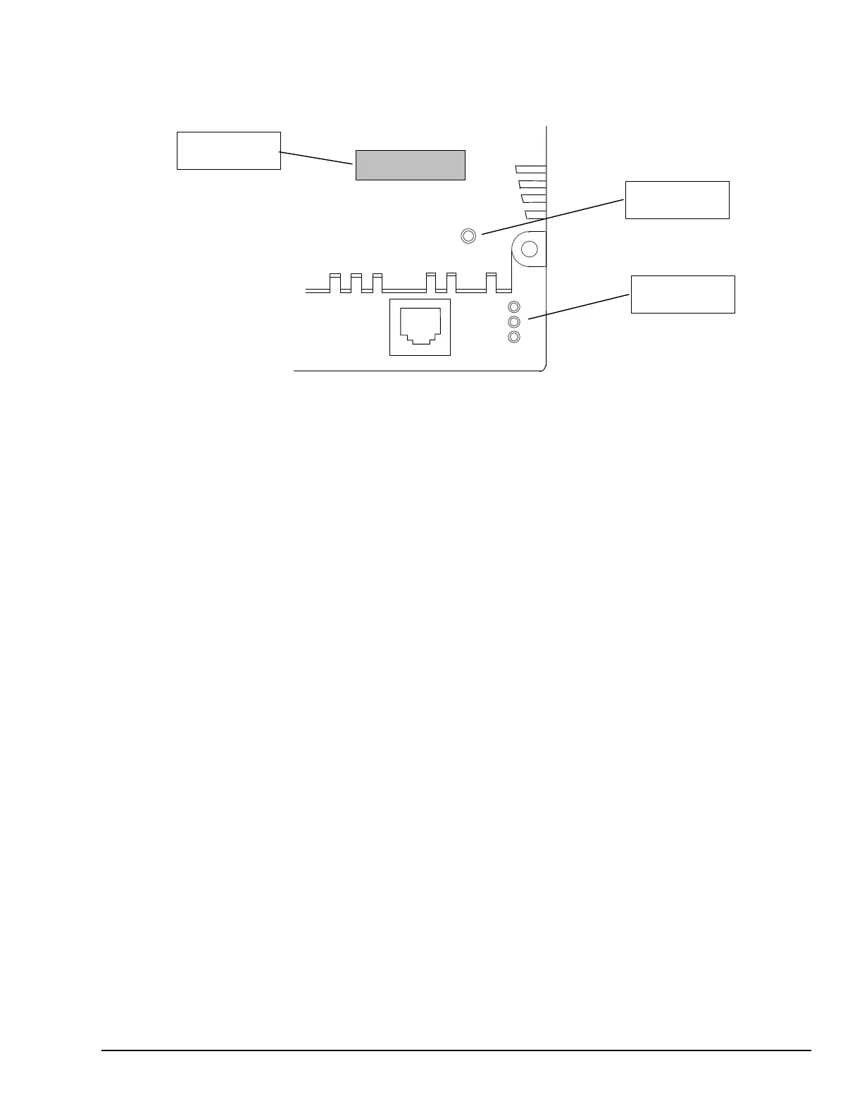
ETHERNET
10 BASE T
ETHERNET
RESTART
Pushbutton
Ethernet
LEDs
IP ADDRESS
IP Address
Writable Area
The Ethernet Restart pushbutton has two functions:
• When pressed for less than 5 seconds, it resets the Ethernet hardware, tests the
Ethernet LEDs, and restarts the Ethernet firmware. This disrupts any Ethernet
communications that are presently underway.
• When pressed for at least 5 seconds, it toggles the function of Port 1 between its
configured operation and forced local Station Manager operation. Note that if Port 1
is available for Local Station Manager operation, Winloader cannot be used for a
firmware upgrade.
3.9 Ethernet LEDs
Three LEDs indicate the status and activity of the Ethernet interface.
LAN indicates the status and activity of the Ethernet network connection. ON/blinking
green indicates Ethernet interface is online.
STAT indicates the general status of the Ethernet interface. ON green indicates no
exception detected. ON amber indicates an exception. Blinking amber indicates error
code. Blinking green indicates waiting for configuration or waiting for IP address.
PORT1 indicates when the Ethernet interface is controlling the RS-232 serial port. It
also indicates when the Ethernet Restart pushbutton has been used to override configured
RS-232 port usage for Local Station Manager operation. ON amber indicates Port 1 is
available for Local Station Manager use (either by configuration or forced). OFF indicates
PLC CPU is controlling Port 1. (Does not blink to indicate traffic).
The Ethernet LEDs turn ON briefly (green) when a restart is performed in the Operational
state by pressing and releasing the Restart pushbutton. This verifies that the Ethernet
LEDs are operational. All three LEDs blink green in unison when a software load is in
progress.
CPU Module Datasheet: CPUE05 GFK-1503E User Manual 47
For public disclosure

 Loading...


