12.4.8 Write Port Control Function (4304)
This function forces RTS for the specified port:
12.4.8.1 Example Command Block for the Write Port Control
Function
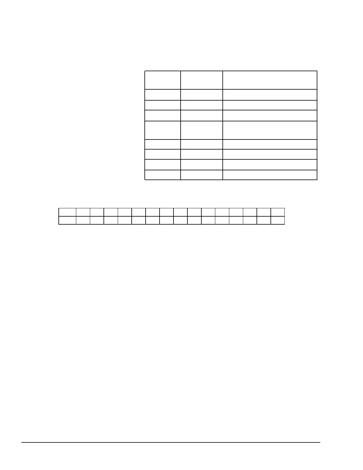
VALUE
(decimal)
VALUE
(hexadecimal)
MEANING
address 0002 0002
Data block length
address +1 0000 0000 NOWAIT mode
address +2 0008 0008
Status word memory type (%R)
address +3 0000 0000
Status word address minus 1 (%
R0001)
address +4 0000 0000 Not used
address +5 0000 0000 Not used
address +6 4304 10D0
Write port control command
address +7
xxxx xxxx
Port control word
12.4.8.2 Port Control Word
15 14 13 12 11 10 9 8 7 6 5 4 3 2 1 0
RTS U U U U U U U U U U U U U U U
The Port Control Word can be:
15 RTS Commanded state of the RTS output
1 = Activates RTS
0 = Deactivates RTS
0-14 U Unused (should be zero)
12.4.8.3 Operating Note
For CPU port 2 (RS-485), the RTS signal is also controlled by the transmit driver.
Therefore, control of RTS is dependent on the current state of the transmit driver. If the
transmit driver is not enabled, asserting RTS with the Write Port Control COMMREQ
will not cause RTS to be asserted on the serial line. The state of the transmit driver is
controlled by the protocol and is dependent on the current Duplex Mode of the port. For
2-wire and 4-wire Duplex Mode, the transmit driver is only enabled during transmitting.
Therefore, RTS on the serial line will only be seen active on port 2 (configured for 2-wire
or 4-wire Duplex Mode) when data is being transmitted. For point-to-point Duplex Mode,
the transmit driver is always enabled. Therefore, in point-to-point Duplex Mode, RTS on
the serial line will always reflect what is chosen with the Write Port Control COMMREQ.
242 GFK-1503E VersaMax PLC User Manual
For public disclosure