28
Conguring Input Channels
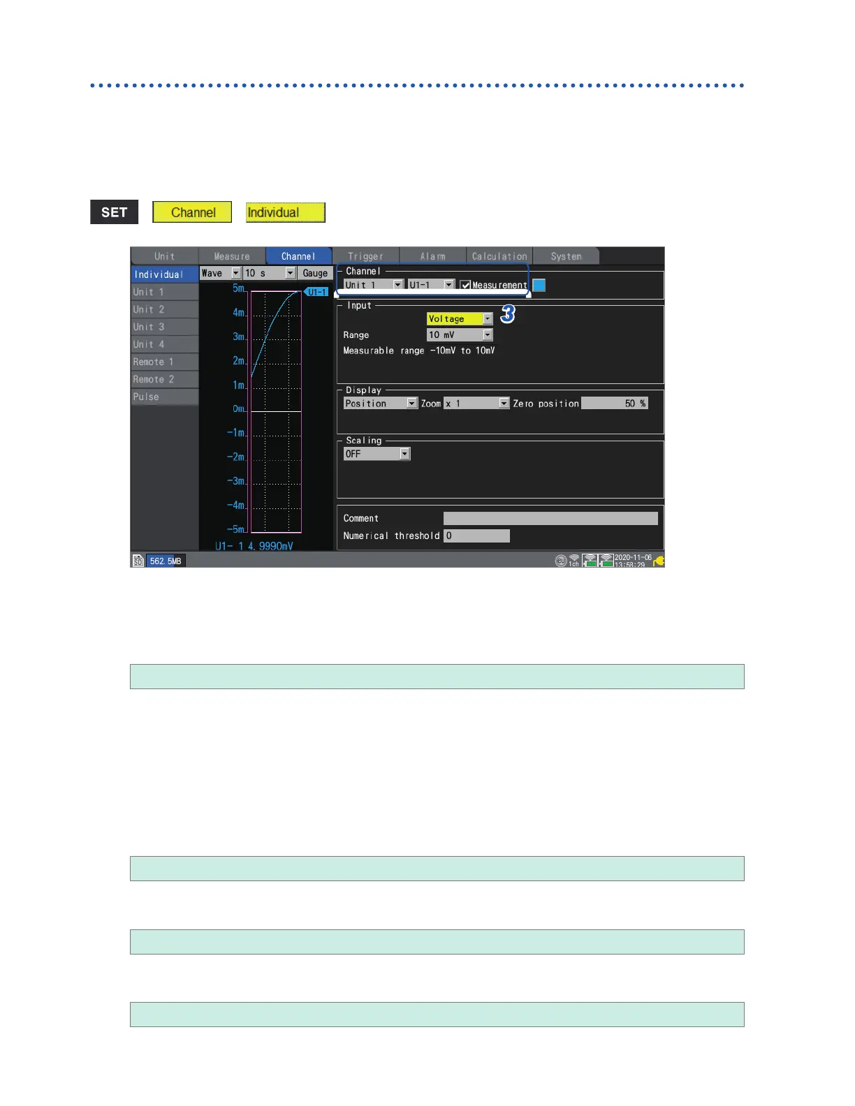
Measuring voltage
This section describes how to congure settings on the individual settings screen when measuring
voltage.
You can use [Input] on the settings list screen to congure the settings. (See p. 67.)
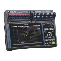
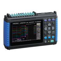
Applicable modules: U8550, U8551, U8552, U8553, U8554, LR8530, LR8531, LR8532, LR8533,
LR8534
> >
3
4
1
2
1
Select the module (Unit) and channel to congure and select the check box.
Measurement will not be performed for channels whose check boxes are not selected.
2
Select the waveform display color.
× (OFF), 24 colors
Select [×] if you wish to measure the channel but not to display its waveform or numerical values on the
screen.
3
Set the input type to [Voltage].
For the U8553 and LR8533, the setting cannot be changed from [Voltage].
4
Under [Range], select the measurement range as appropriate for the measurement target.
The measurable range of the selected range will be displayed.
(For the U8550, U8551, U8552, LR8530, LR8531, or LR8532)
10 mV
, 20 mV, 100 mV, 200 mV, 1 V, 2 V, 10 V, 20 V, 100 V, 1 to 5 V
(For the U8553 or LR8533 High Speed Voltage Unit)
100 mV
, 200 mV, 1 V, 2 V, 10 V, 20 V, 100 V, 1 to 5 V
(For the U8554 or LR8534 Strain Unit)
1 mV
, 2 mV, 5 mV, 10 mV, 20 mV, 50 mV, 100 mV, 200 mV
www.GlobalTestSupply.com
Find Quality Products Online at: sales@GlobalTestSupply.com

 Loading...