74
Conguring Channels in a List
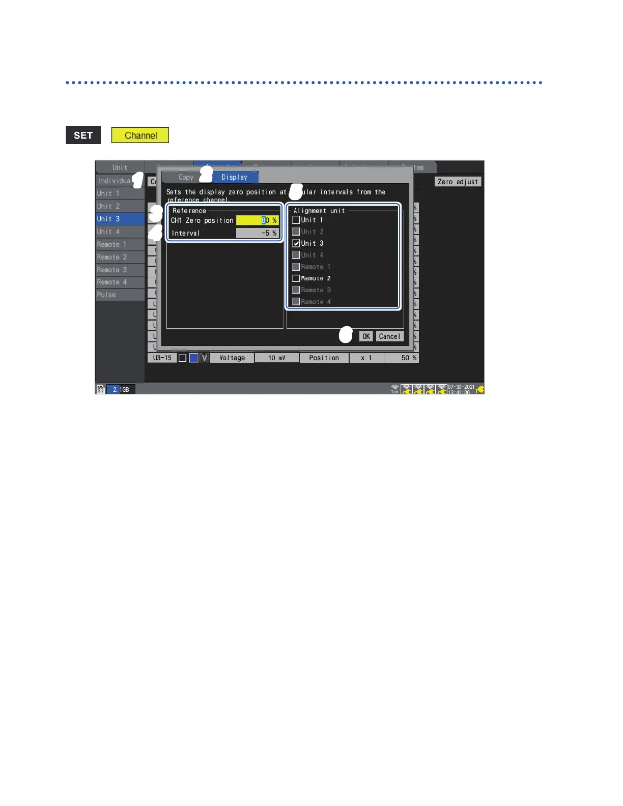
Aligning waveforms’ zero positions
This section describes how to align zero positions for displayed waveforms at a specied interval
based on channel 1 of the sub tab unit.
> > [Unit n] (n = 1, 2, . . .)
1
3
6
2
5
4
1
Press the ENTER key while [Copy…] is selected.
The settings window will open.
2
Using the up and down keys, select the [Display] tab.
3
Under [CH1 Zero position] under [Reference], set the zero position for the reference channel
(CH1).
4
Under [Interval] under [Reference], set the interval for uniform alignment.
5
Under [Alignment unit], select the checkboxes for the units whose zero positions you wish
to align.
6
Select [OK] and press the ENTER key.
• Alignment is only valid for the reference channel and channels whose copy destination channel
display setting is [Position].
• The range for the reference channel’s zero position varies with the zoom factor.
• If [Interval] is negative, zero positions will be shifted from the reference channel’s zero position
in the negative direction at a set interval; if it’s positive, they’ll be shifted similarly in the positive
direction.
• Alignment is valid for units with the same number of channels in the same system.
U8550 and LR8530 (Voltage/Temp Units, 15 channels of plug-in and wireless modules)
U8551 and LR8531 (Universal Units, 15 channels of plug-in and wireless modules)
U8552 and LR8532 (Voltage/Temp Units, 30 channels of plug-in and wireless modules)
U8553 and LR8533 (High Speed Voltage Units, 5 channels of plug-in and wireless modules)
U8554 and LR8534 (Strain Units, 5 channels of plug-in and wireless modules)
• If the maximum or minimum value for the zero position is exceeded due to the zoom factor at the
time of alignment, the maximum or minimum value will be used.
www.GlobalTestSupply.com
Find Quality Products Online at: sales@GlobalTestSupply.com

 Loading...