374
Measuring Strain
11.2 Measuring Strain
For information about the connection of strain gages see “Connecting a strain gage or converter” in the
Quick Start Manual. .
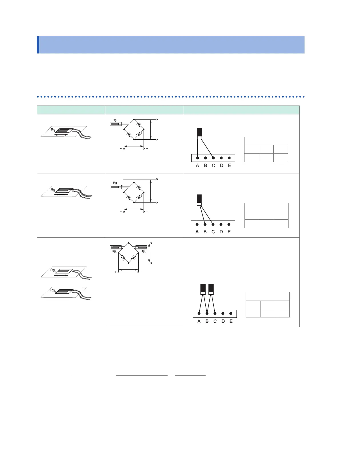
Tension and compression on a single axis
Gage method Bridge circuit diagram Connection to U8554 or LR8534
1-gage method (2-wire)*
1
Applied voltage
E
Output
voltage
e
e =
ε
(
ε
: Strain)
This is the most typical connection method
DIP switch
OFF ON ON
1 2 3
Rg
1-gage method (3-wire)*
1
Applied voltage
E
Output
voltage
e
e =
ε
(
ε
: Strain)
This connection method cancels the eects of
temperature on the strain gage wiring.
DIP switch
OFF ON OFF
1 2 3
Rg
2-gage method
(adjacent side)
(active dummy method)*
1
Active gage
Dummy gage
Applied voltage
E
Output
voltage
e
e =
ε
(
ε
: Strain)
In this connection method, a reference strain
gage is axed to a specimen made of the same
material as the measurement target that is
not being subjected to stress. Apparent strain
resulting from temperature changes is measured
using the reference gage and canceled out.
DIP switch
ON ON OFF
1 2 3
Rg
1
Rg
2
*1: Must be corrected using (1,000,000 × measured value) / (1,000,000 - measured value). The
scaling function cannot be used to perform correction. Instead, perform correction using the
waveform calculation function.
Example: True strain value if the instrument measures a strain value of 50,000 μ
ε
while using the
1-gage/2-wire method
ε
i
: True strain value
ε
: Strain value measured by instrument
ε
i
=
(1,000,000 × ε)
(1,000,000 − ε)
=
(1,000,000 × 50,000)
(1,000,000 − 50,000)
=
50,000 × 10
6
950,000
≈
52632
(με)
www.GlobalTestSupply.com
Find Quality Products Online at: sales@GlobalTestSupply.com

 Loading...