43
Conguring Input Channels
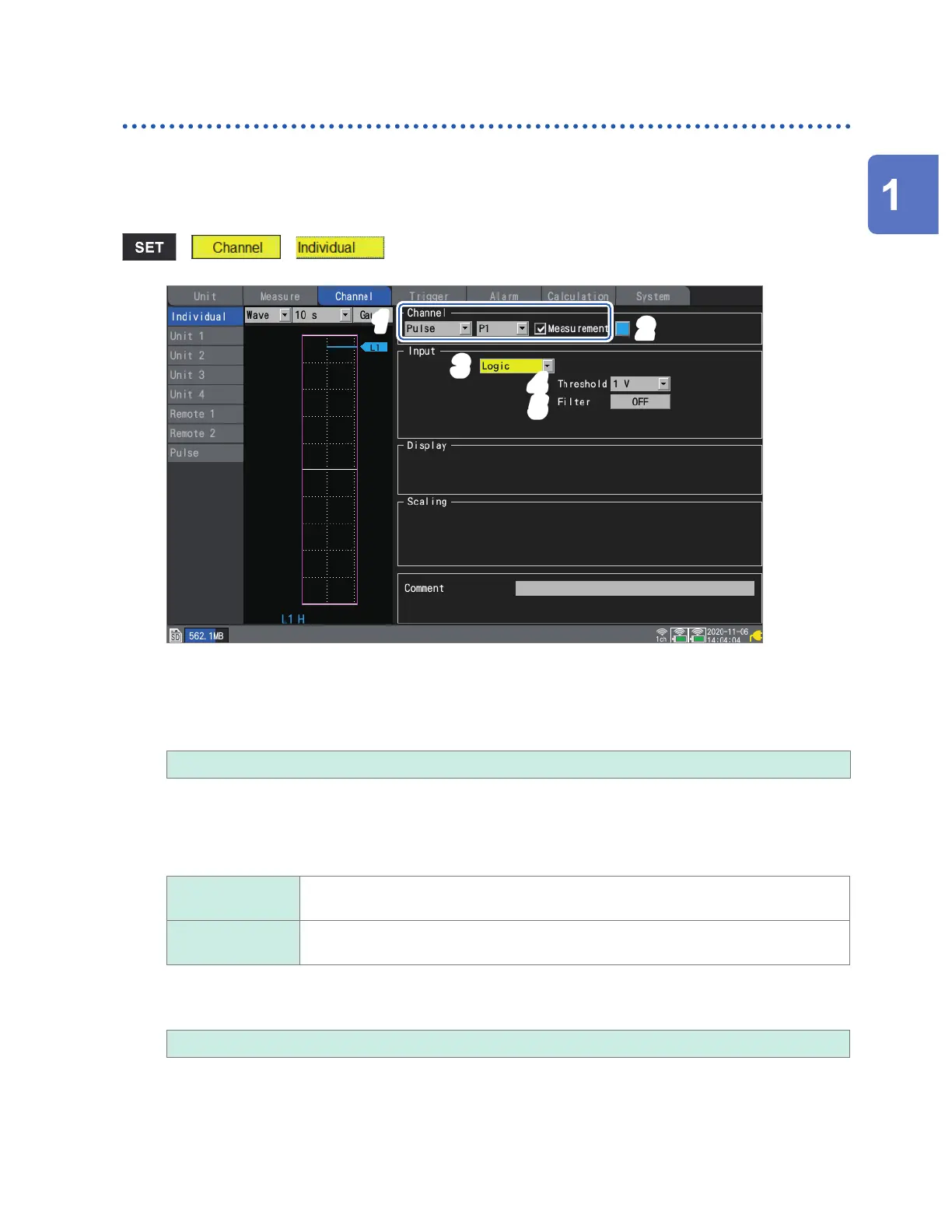
Measuring logic signals
This section describes how to congure settings on the individual settings screen when measuring
logic signals.
You can use the settings list screen to congure the settings. (See p. 69.)
External control terminals: Pulse input terminals P1 to P8
> >
4
1
3
5
2
1
Select [Pulse], and choose a channel from [P1] to [P8],
Measurement will not be performed for channels whose check boxes are not selected.
2
Select the waveform display color.
× (OFF), 24 colors
Select [×] if you wish to measure the channel but not to display its waveform on the screen.
3
Set the input type to [Logic].
4
Under [Threshold], select the level to count.
1 V
Treats voltages that are greater than or equal to 1.0 V as high level and voltages that
are greater than or equal to 0 V but less than 0.5 V as low level.
4 V Treats voltages that are greater than or equal to 4.0 V as high level and voltages that
are greater than or equal to 0 V but less than 1.5 V as low level.
5
Under [Filter], select whether to use the chatter prevention lter.
Set to [ON] to prevent false counting due to chatter in mechanical contact (relay) output.
OFF
, ON
Settings and Operation
www.GlobalTestSupply.com
Find Quality Products Online at: sales@GlobalTestSupply.com

 Loading...