EasyManuals Logo
Home>Hioki>Data Loggers>MEMORY HiLOGGER LR8450

Hioki MEMORY HiLOGGER LR8450 User Manual

Hioki MEMORY HiLOGGER LR8450
425 pages
To Next Page IconTo Next Page
To Previous Page IconTo Previous Page
Page #411 background imageLoading...
Page #411 background image
406
Input Circuit Schematics
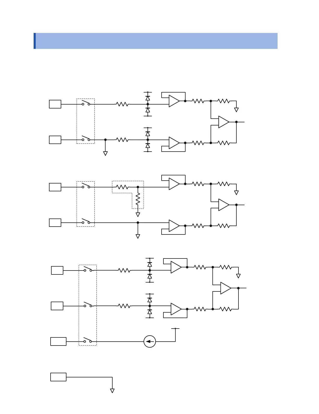
11.13 Input Circuit Schematics
This section provides input circuit schematics for the instrument.
Analog input circuit: U8550, U8551, U8552, LR8530, LR8531, LR8532
Voltage (10 mV f.s. to 2 V f.s. ranges), thermocouple
Channel switching relay
Voltage (10 V f.s. to 100 V f.s. ranges, 1-5 V f.s. range), humidity
Channel switching relay
1 M
Ω
Resistance temperature detector (4-wire), resistance
SoH
SoL
Channel switching relay
Constant-current circuit
SoL terminal is common to all channels.
HIOKI LR8450A964-03
www.GlobalTestSupply.com
Find Quality Products Online at: sales@GlobalTestSupply.com

Table of Contents

Other manuals for Hioki MEMORY HiLOGGER LR8450

Questions and Answers:

Question and Answer IconNeed help?

Do you have a question about the Hioki MEMORY HiLOGGER LR8450 and is the answer not in the manual?

Hioki MEMORY HiLOGGER LR8450 Specifications

General IconGeneral
BrandHioki
ModelMEMORY HiLOGGER LR8450
CategoryData Loggers
LanguageEnglish

Related product manuals