80
Observing Waveforms
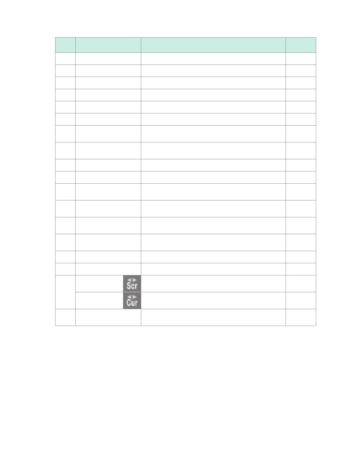
No. Name Description
Reference
page
10
Channel selection Allows you to select the channel to congure. –
11
Measurement Allows you to turn measurement on or o. p. 28
12
Waveform color Allows you to select the waveform display color. p. 28
13
Input type Allows you to select the type of input. p. 25
14
Range Allows you to select the range. p. 25
15
Display position Allows you to select the waveform display position. p. 52
16
Zoom factor Allows you to select the zoom factor in the voltage axis
direction.
p. 52
17
Zero position Allows you to set the waveform's display position (zero
position).
p. 52
18
Zero adjustment Allows you to perform zero adjustment. p. 76
19
Auto-balancing Allows you to perform auto-balancing (Strain Units only). p. 37
20
Gage B Indicates the channels and modules displayed using gage
B.
p. 85
21
Gage A Indicates the channels and modules displayed using gage
A.
p. 85
22
Trigger time Indicates the time and date at which the trigger was
activated.
–
23
Status bar Displays the time and date, messages, icons*
1
, and other
information.
–
24
Time value Displays the time from the measurement start.*
2
–
25
Scroll bar Indicates the displayed waveform’s range and position. p. 91
26
Scroll icon
The waveform is moved using the SCROLL/CURSOR
keys.
p. 89
Cursor icon
The A/B cursors are moved using the SCROLL/CURSOR
keys.
p. 95
27
Follow The most recent waveform is always displayed using the
auto-scroll function.
–
*1: For more information about icons other than the scroll and cursor icons, see “Screen and icons” in “1.2 Part
Names and Functions; Screens” in the Quick Start Manual.
*2: The waveform screen, value screen, and warning screen of the instrument express minute, a unit of time,
in terms of the letter m instead of min.
www.GlobalTestSupply.com
Find Quality Products Online at: sales@GlobalTestSupply.com

 Loading...