5.1.3 Printed circuit board for RPC, RPF(I), RPI(M) units
C A U T I O N
Turn off the power supply before setting the DIP switches. If not, the settings will not be valid.
N O T E
• The following information is not valid for RPI-(8.0/10.0)FSN2E indoor units.
• The symbol “■” indicates the position of the DIP switches. The figures show the setting before transmission
or after selection.
• If the “■” mark is not displayed, this indicates that the position of the pin is not affected.
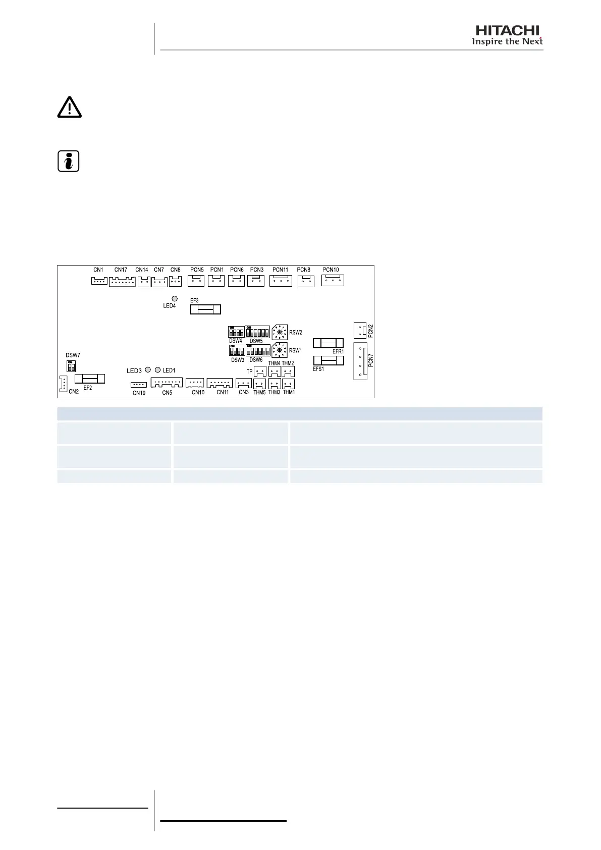
The indoor unit PCB operates with four types of DIP switches, a slide switch and a rotary switch. The position is as follows:
LED indicator
LED1 Red
This LED indicates the transmission status between the indoor unit and the
remote control.
LED3 Yellow
This LED indicates the transmission status between the indoor unit and the
outdoor unit.
LED4 Green PCB power supply
5 Control system
166
SMGB0063 rev. 1 - 10/2010

 Loading...