RPK-(2.0/4.0)FSN(H)2M
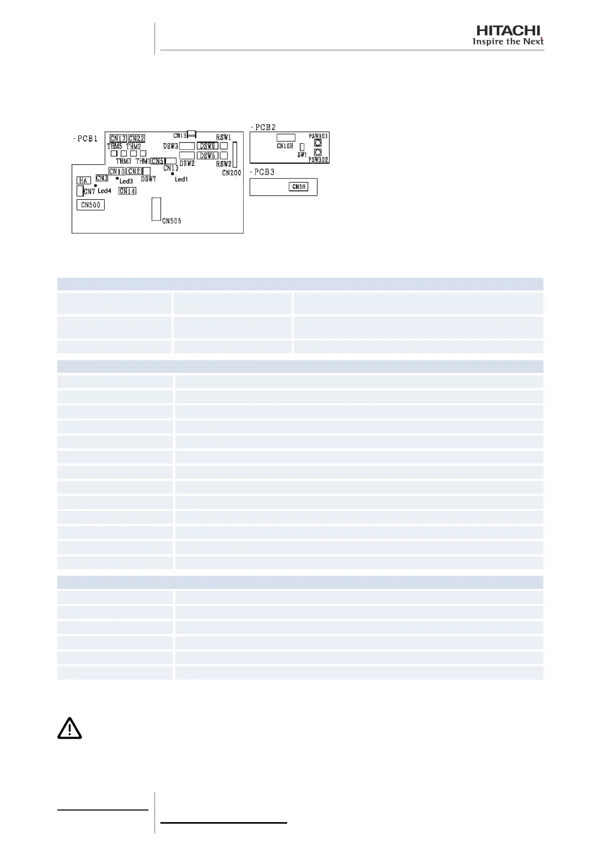
The indoor unit PCB operates with four types of DIP switches, a slide switch, a rotary switch and a button switch. The
position is as follows:
LED indicator
LED1 Red
This LED indicates the transmission status between the indoor unit and the
remote control.
LED3 Yellow
This LED indicates the transmission status between the indoor unit and the
outdoor unit.
LED4 Red PCB power supply
Connector indication
THM1 Air inlet
THM2 Air outlet
THM3 Freeze protection
THM5 Gas pipe
CN2 Outdoor unit H-LINK control circuit
CN3 Optional input functions
CN5 PCB3 connection
CN7 Optional output functions
CN13 SW remote control
CN14 Expansion valve control
CN17 Swing louver motor
CN10 Connection of the PCB3 wireless receiver part
CN550 Fan motor
Switch indication
PSW301, PSW302 Changeover switch for emergency operation
DSW6, RSW1 Indoor unit setting
DSW5, RSW2 Refrigerant cycle number
DSW2 Optional functions
DSW3 Capacity code
DSW7 Fuse re-establishing
5.1.6 Printed circuit board for KPI complementary systems
C A U T I O N
Turn off the power supply before setting the DIP switches. If not, the settings will not be valid.
5 Control system
172
SMGB0063 rev. 1 - 10/2010

 Loading...