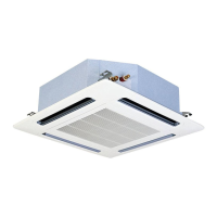
Remove the cap nut and the washer securing the fan duct and
remove it.
N O T E
• Torque value: maximum 8 Nm.
• RCD-(1.5-3.0)FSN2: one duct and one fan motor.
• RCD-(4.0-5.0)FSN2: two ducts and two fan motors.
Separate the connector from the fan motor earth cable.
Remove the four nuts securing the fan motor and remove it.
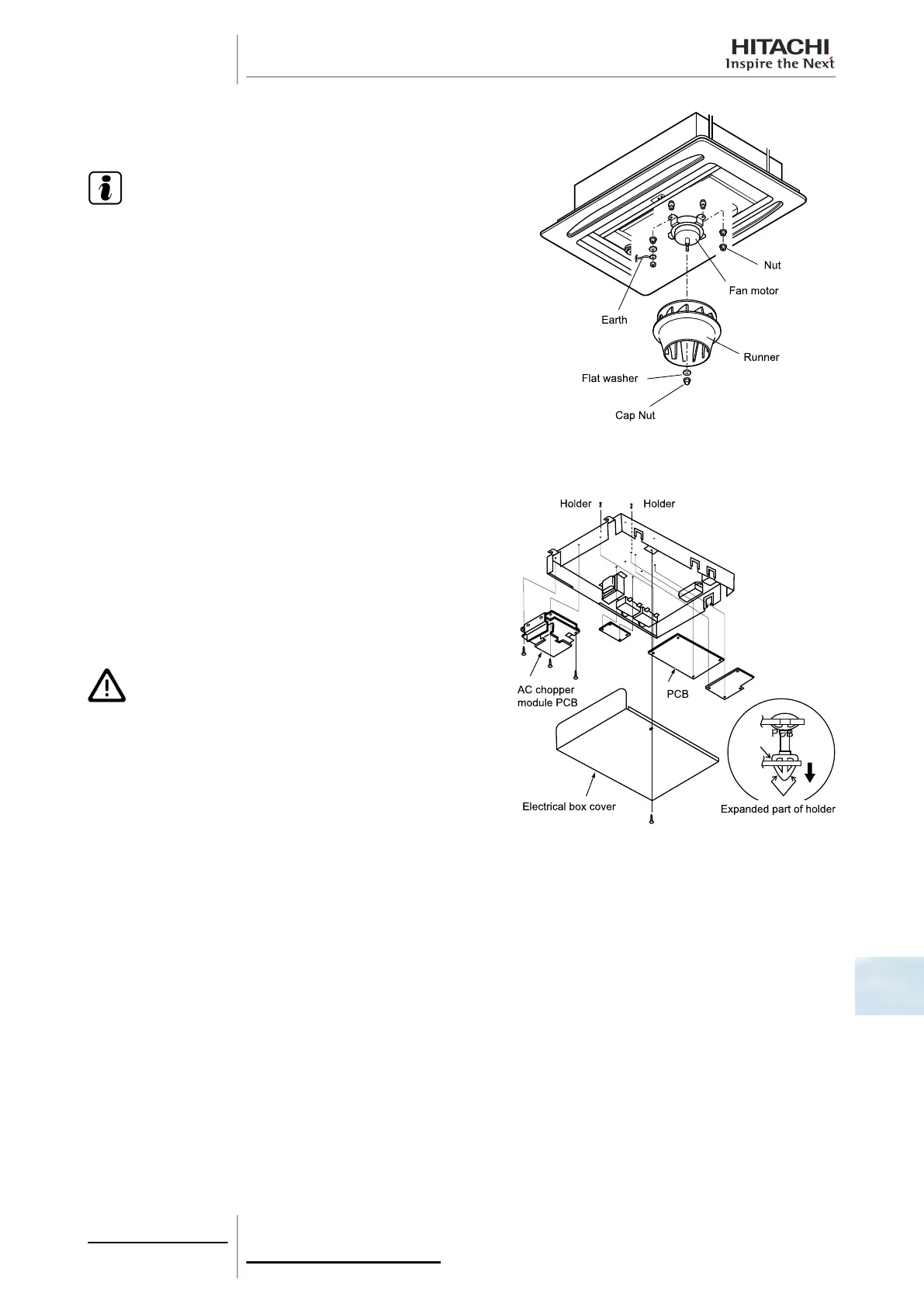
10.3.5 Removal of the printed circuit board (PCB)
Remove the air inlet grille as indicated in chapter Removal of the
optional air panel, see on page 287.
Remove the electrical box as indicated in chapter Removal of the
electrical box, see on page 287.
Remove the printed circuit board (PCB) by pressing carefully on
the support tabs with long-tipped pliers, as shown in the figure.
Remove the three set screws from the AC chopper.
C A U T I O N
• Do not touch the electrical components of the PCB.
• Do not apply force to the PCB, as this could damage it.
• The sealed earthing cable and the transformer are secured
by a screw. When installing, be particularly careful not to
overtighten the set screw.
10 Servicing
289
SMGB0063 rev. 1 - 10/2010
10

 Loading...