C A U T I O N
• Do not touch the electrical components of the PCB.
• Do not apply force to the PCB, as this could damage it.
• Pay special attention to the position of the connectors on the PCB. An incorrect position during installation
may damage the PCB.
10.9.7 Removal of the thermistors from the liquid and gas piping
Remove the air inlet grille as indicated in section Removal of the
air inlet grille, see on page 346.
Remove the air filter as indicated in section Removal of the air
filter, see on page 346.
Remove the front panel as indicated in Section Removal of the front
panel, see on page 347.
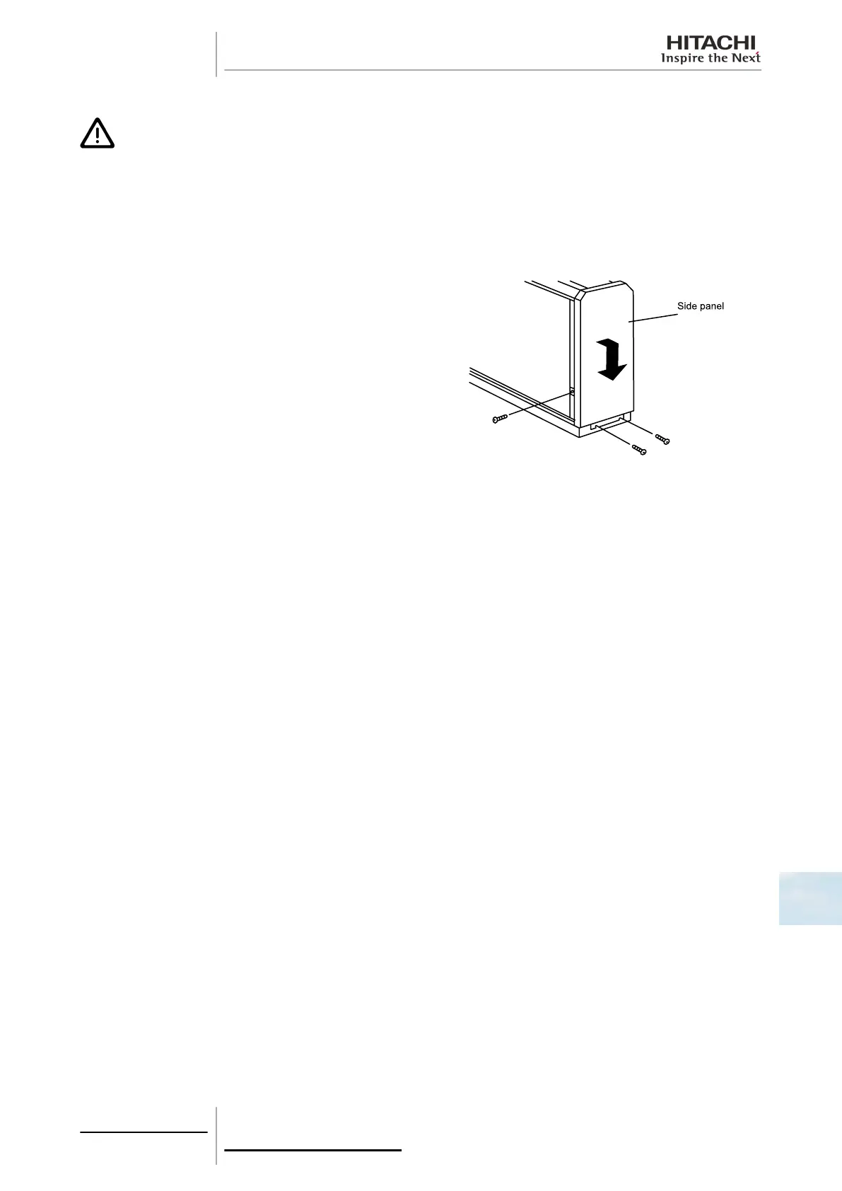
Remove the side panel, removing the 3 set screws and pulling the
panel downwards.
Disconnect the wiring from the thermistor and remove the
thermistor.
10.9.8 Removal of the fan motor
Remove the air filter in line with the instructions given in chapter Removal of the air filter, see on page 346.
Remove the front panel in line with the instructions given in chapter Removal of the front panel, see on page 347.
Remove the motor in line with the instructions given in chapter Removal of the fan motor, see on page 347.
10.9.9 Removal of the printed circuit board (PCB)
Remove the front panel in line with the instructions given in chapter Removal of the front panel, see on page 347.
Remove the PCB following the instructions given in chapter Removal of the printed circuit board (PCB), see on page 349.
10.9.10 Removal of the thermistors from the liquid and gas piping
Remove the air filter in line with the instructions given in chapter Removal of the air filter, see on page 346.
Remove the front panel in line with the instructions given in chapter Removal of the front panel, see on page 347.
Remove the thermistors in line with the instructions given in chapter Removal of the thermistors from the liquid and gas
piping, see on page 349.
10 Servicing
349
SMGB0063 rev. 1 - 10/2010
10

 Loading...