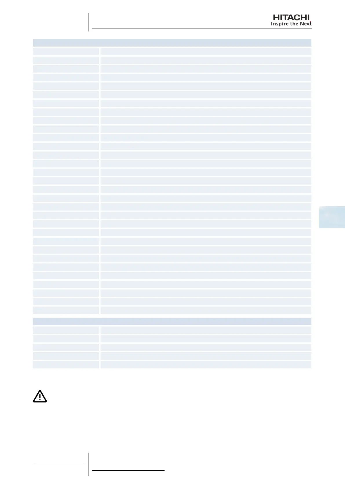
Connector indication
PCN1 220 V transformer
PCN2 Indoor fan motor internal thermostat
PCN3 Not used
PCN5 Not used
PCN6 Drain pump motor (RPI)
PCN7 Power supply (1-R, 2-S, 3-N, 4-E)
PCN8 Capacitor
PCN10 Fan motor power supply
PCN11 Fan motor speed control
PCN301 Terminal board connections
PCN302 PCB2 connection
THM1 Air inlet
THM2 Air outlet
THM3 Liquid pipe
THM4 Remote thermistor (THM-R2 AE)
THM5 Gas pipe
TP Not used
EF3 Fuse
EF2 Fuse
EFS1 Fuse
EFR2 Fuse
CN1 Transformer (pins 1-2: 17.3 V/pins 3-4: 20.8 V)
CN2 Outdoor unit H-LINK control circuit
CN3 Optional input functions (only 2)
CN7 Optional output functions (only 2)
CN8 Optional output functions (no. 1, no. 2, only 1)
CN11 Expansion valve control
CN12 Remote control jumper connection for several units
CN13 SW remote control
CN14 Float switch (RPI)
CN17 Swing louver motor
Switch indication
DSW3 Capacity code
DSW4 Unit model code
DSW5, RSW2 Refrigerant cycle number
DSW7 Fuse recovery and remote control selector
DWS6, RSW1 Indoor unit number settings
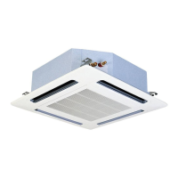
5.1.4 Printed circuit board for RPI-(8.0/10.0) FSN2E units
C A U T I O N
Turn off the power supply before setting the DIP switches. If not, the settings will not be valid.
5 Control system
167
SMGB0063 rev. 1 - 10/2010
5

 Loading...