10.5.4 Removal of the thermistors from the liquid and gas pipes
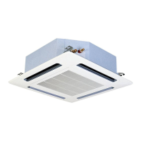
Remove all screws -A- from the lower cover of the unit and separate
it.
Remove the electrical box cover Removal of the electrical box
cover, see on page 303.
Disconnect the thermistor.
N O T E
• To disconnect and remove the appropriate thermistor,
previously see the chapter corresponding to the wiring
diagrams in this Manual.
• Black connector: liquid thermistor.
• Yellow connector: gas thermistor.
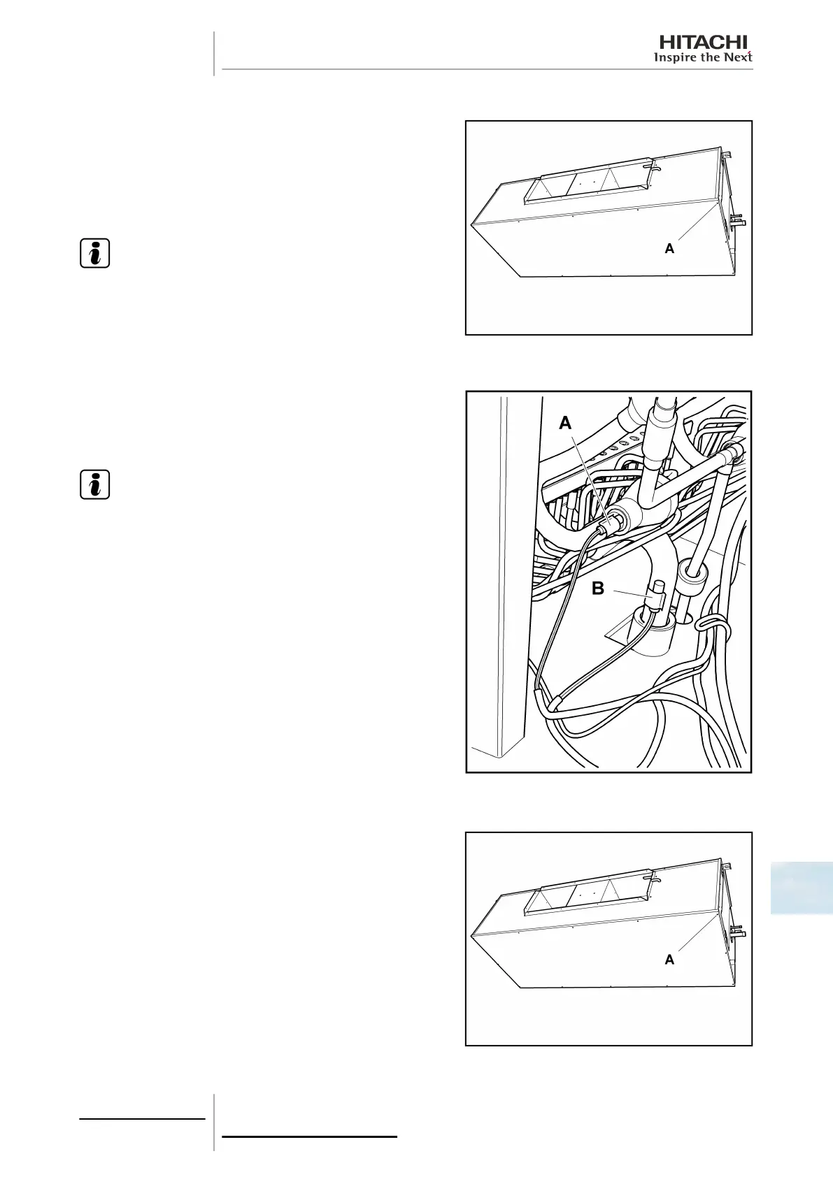
Remove the gas -A- and liquid -B- thermistor insulation cover.
Remove the special clamp holding the thermistor to the copper
piping and remove it.
N O T E
When fitting the thermistors, remember that they must be
secured correctly by the special clamp and completely
covered by the previously removed insulation.
10.5.5 Removal of the drain pan
Remove all screws -A- from the lower cover of the unit and separate
it.
Release the unit drainage connection.
10 Servicing
305
SMGB0063 rev. 1 - 10/2010
10

 Loading...