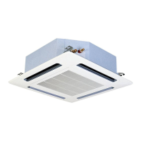
10.3.6 Removal of the float switch
Remove the air inlet grille as indicated in chapter Removal of the
long-lasting filter and the air inlet grille, see on page 287.
Remove the bellmouth in line with the instructions given in chapter
Removal of the fan duct and the fan, see on page 288.
Remove the two screws securing the panel located next to the
service opening, close to the pipes inside the unit and remove it.
Separate the float switch connector and remove the two screws
securing the plate attaching the switch to the drain mechanism
securing plate.
Loosen the resin nut securing the float switch and remove it.
N O T E
The torque value of the resin nut is 0.3 - 0.4 Nm. If the torque
value is higher, the nut will be damaged.
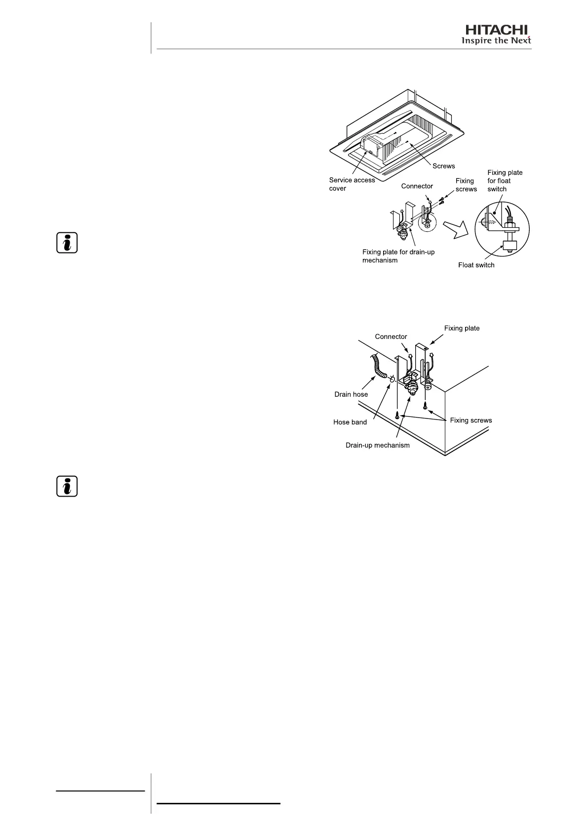
10.3.7 Removal of the drain mechanism
Remove the air inlet grille as indicated in chapter Removal of the
long-lasting filter and the air inlet grille, see on page 287.
Remove the bellmouth in line with the instructions given in chapter
Removal of the fan duct and the fan, see on page 288.
Remove the drain pan as indicated in chapter Removal of the drain
pan, see on page 291.
Separate the connectors from the drain pump and the float switch.
Remove the flange from the hose and remove the drain hose.
Remove the two screws from the plate securing the drain
mechanism and remove it.
N O T E
When installing, fit the drain hose as far as possible in the pump.
10 Servicing
290
SMGB0063 rev. 1 - 10/2010

 Loading...