ID50 Series Panel - Installation, Commissioning & Configuration Manual
Installation Guide
12997-263-000-11, Issue 11
January 2010
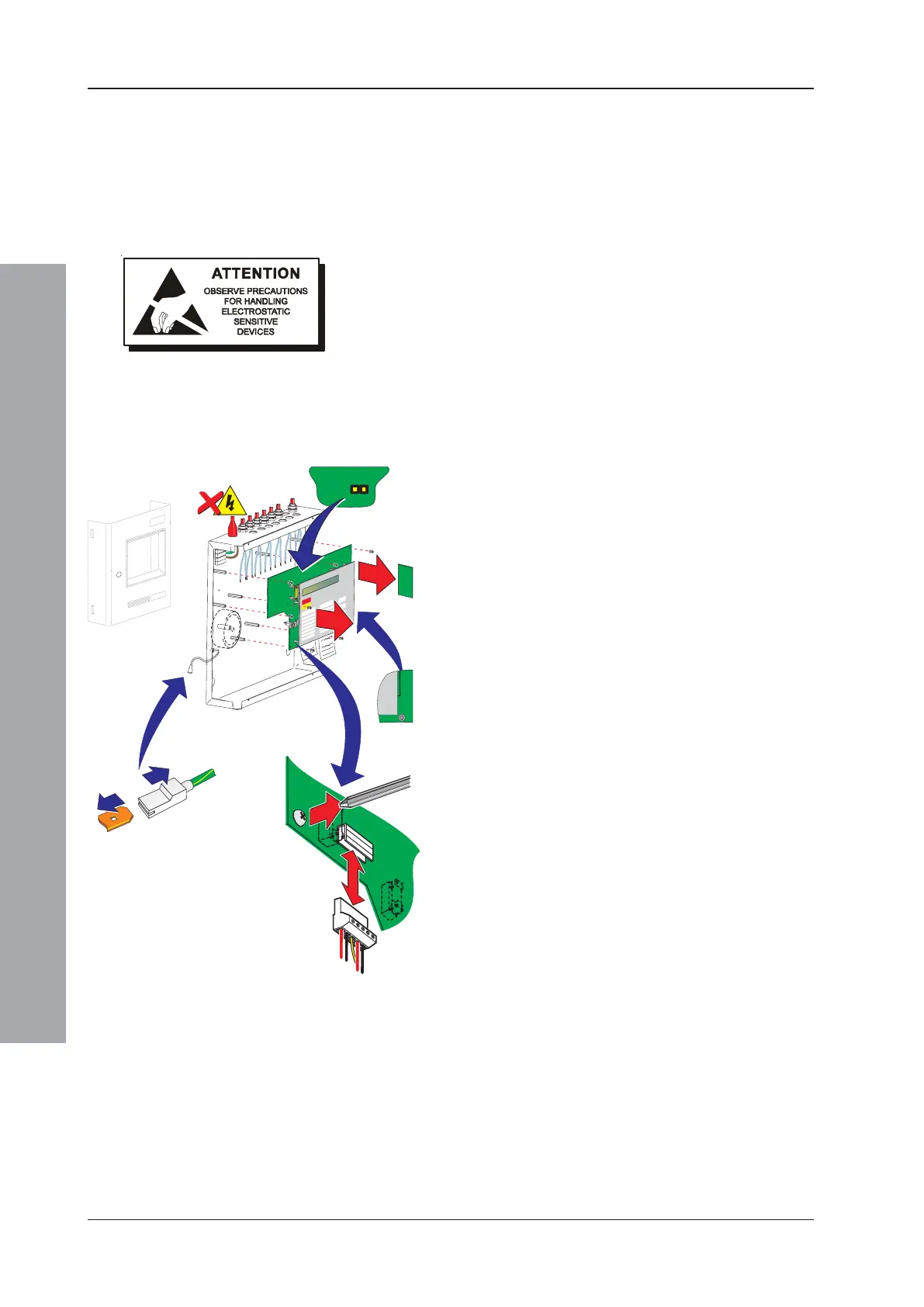
2.5.2 Removing the Panel Electronics
The ID50 Series Panel electronics comprises the PCB
assembly with mounted LCD unit and the mounted fascia.
These are supplied as one spared item in kit
PN: 020-635-XXX. This assembly is located within the
back box, but should ONLY be removed when installing
the back box or if the PCB requires replacement.
CAUTION: The electronic circuits of the ID50 Series
Panel use CMOS devices which can be damaged by
static discharge. Suitable precautions MUST be taken
when handling circuit boards.
Procedure
When installing the back box or, if it becomes necessary
to remove the PCB assembly for another reason, follow
this recommended procedure:
1 Remove the cover and store in a safe place, see
Section 2.5.1, Removing the Cover. Then make a
back-up of the current system configuration,
remembering to disconnect the link at jumper J19.
Note: The blade connection to the cover fitted in back
boxes incorporates a locking barb. To remove this
connection, pull the shroud (B), NOT the earth wire,
from the earth blade terminal (A).
2 Isolate the mains power supply and disconnect the
battery interlink wire if fitted.
3 At the two-part connector TB1 (on the PCB assembly),
using a constant pulling action carefully disconnect
the mains and battery power supply wiring.
4 Taking suitable anti-static precautions remove the
RS485 Interface PCB, if fitted (refer to Section 2.7.1,
Installing the RS485 Interface Module PCB).
5 At the PCB assembly, note the polarity and
connections of all cables and any jumper configuration
settings. Using a screwdriver, loosen all the connector
securing screws. Carefully secure all external cable
tails away from the electronics and from the back box.
6 Using a No. 1 Posidriv screwdriver, remove the eight
(8) M3 x 8mm clinch screws from the PCB assembly.
Gently lift the PCB assembly clear of the supporting
pillars, place it in an anti-static bag and store safely.
Note: If the PCB is to be returned to the manufacturer
note its Serial Number and Revision Level (located
along one edge).
4
3
4i
6
394-191 iss
ue XXX

 Loading...


