ID50 Series Panel - Installation, Commissioning & Configuration Manual
Commissioning
26997-263-000-11, Issue 11
January 2010
4.4.1 Loop Wiring
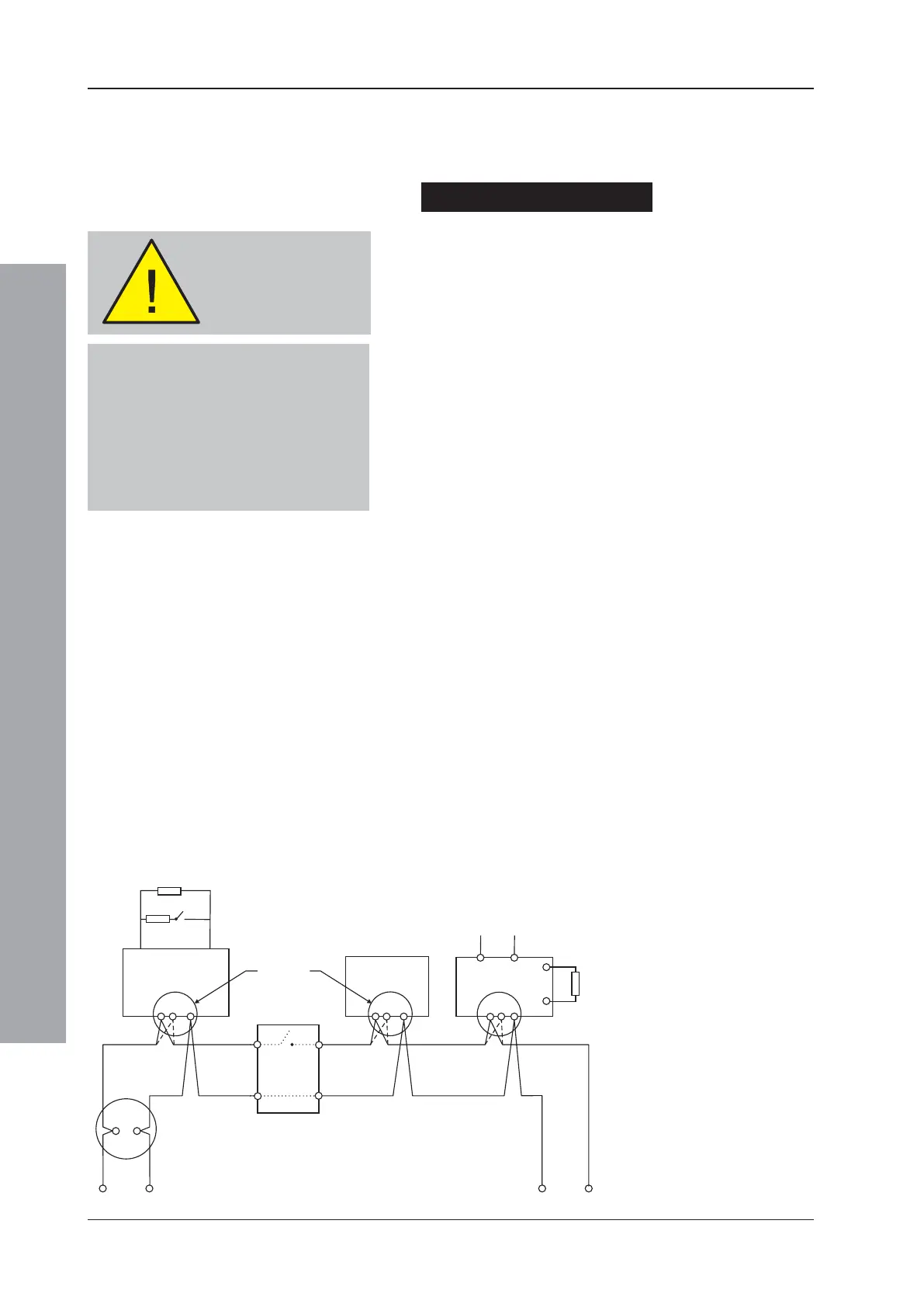
Typical connections of analogue addressable loop pair
to a loop are shown below.
Checks Before Connection
To check the Loop wiring:
1 For CLIP devices link out any isolators on the Loop
by temporarily shorting terminals 2 and 4 on each
isolator. For OPAL protocol-compatible sensor bases
(B501 AP) remove the device from the base. These
bases have +leg terminals (+2 OUT and +4 IN) that
connect automatically when the sensor is removed.
Check Appendix 1 of this manual or the LBC for OPAL
device types fitted with internal isolators.
2 These tests should then be carried out using a low-
voltage multimeter. Check the continuity of each leg
of the loop and measure the end-to-end resistance.
Verify that the total loop resistance (sum of both legs)
is less than 40 ohms. Typically, this will allow a
maximum loop length of 2,000m of screened 1.5mm
2
cable.
Note: The cable capacitance should be less than 0.5μF.
3 Connect the meter in ‘normal’ polarity (+ve to loop +ve
and -ve to loop -ve). The meter should initially read low
resistance but this should increase as the capacitor in
each of the loop devices charges. If the meter indicates
the presence of a forward-biased diode then it is
probable that one or more of the loop devices is
connected in reversed polarity or the wiring is crossed.
4 If reversed device(s) are indicated in step 3, they may
be located by successive halving of the loop (if the
site layout makes this difficult, the affected section of
the loop can be identified from the panel fault
messages after the system has been configured and
the links in the isolators removed - CLIP devices only).
The loop wiring MUST
be disconnected from
the panel during this
procedure
+
-
18k
Monitor used
as input
(see Note a)
4k7
B501/B501 AP
A
M500KAC/
M700KAC
Isolator
(see Note b)
Output
Module
47k
Supervised
Load
28V Supply
Loop Finish
+
-
Loop Start
See Note c
See Note c
See Note c
LOOP IN LOOP OUT LOOP OUT LOOP OUTLOOP IN LOOP IN
OPAL Protocol Devices
Most OPAL devices have internal isolators.
With OPAL-compatible bases the isolator is
connected across terminals +2 and +4 on
the positive loop leg. OPAL devices will
work satisfactorily on B501 bases except
the internal isolator, when fitted, cannot
be operated.
a. A = Normally open switch
- closes under an alarm
condition.
b. To comply with the
requirements of EN54,
isolators should be fitted
between a maximum of
32 loop devices. For the
ID50 Series Panel, do not
place more than 25 loop
devices between isolators
(20 if FET isolators are
used).
c. Refer to device
instruction sheet for
wiring terminations.
Notes:

 Loading...


