ID50 Series Panel - Installation, Commissioning & Configuration Manual
Commissioning
27 997-263-000-11, Issue 11
January 2010
Connecting to the Panel
When the Loop wiring has been checked and found to
be satisfactory, do the following:
1 Remove the temporary links on the isolator units
(OPAL protocol-compatible sensor bases, B501 AP,
automatically link out so these can be ignored at any
addresses where devices with an internal isolator are
installed).
2 Connect the loop wiring to the panel.
When connecting, observe correct polarity! The
ends nominated as + and - must be fitted to the
correct terminals.
3 When the Loop wiring has been connected, apply the
mains supply and then fit the interlink wire to the
batteries.
4 Check the LCD and LEDs for indications of any faults.
If faults exist, correct them and reset the panel.
5 Configure the Loop following the procedures in
Section 5.6.1, Signalling Line Circuit (SLC) -
Devices and/or Section 5.6.2, Signalling Line
Circuit (SLC) - Learn.
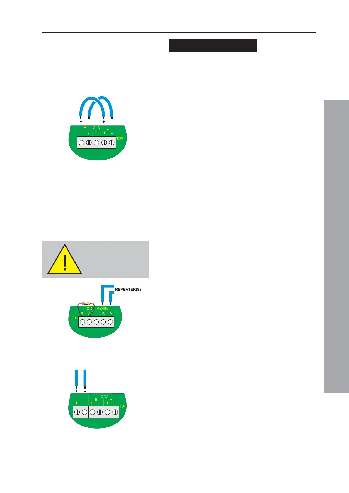
4.4.2 RS485 Communications Link
When the RS485 Communications link has been installed
in the back box, checked and found to be satisfactory:
1 Connect the RS485 Communications Link to the panel
at terminal block TB6, located on the PCB assembly,
as shown at left.
When connecting, observe correct polarity! The
ends nominated as B and A must be fitted to the
correct terminals.
2 When the RS485 Communications link has been
connected, apply the mains supply and then fit the
interlink wire to the batteries.
4.4.3 DC Auxiliary Output
BEFORE connecting any circuit to the monitored DC
Auxiliary Output, check that:
1 The external wiring is not short circuit.
2 There are no forward-biased diodes (as used for
example with end-of-line power monitoring relays)
connected across the external wiring.
When connecting, observe correct polarity! The
ends nominated as + and - must be fitted to the
correct terminals.
Apply power
BEFORE making any
RS485 connections.

 Loading...


