ID50 Series Panel - Installation, Commissioning & Configuration Manual
Installation Guide
13 997-263-000-11, Issue 11
January 2010
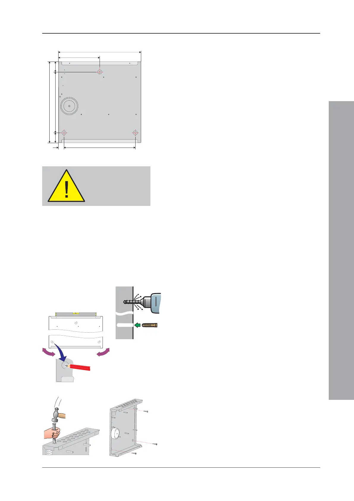
2.5.3 Back Box Fixing
The ID50 Series Panels (PN: 002-455-XXX) are 110mm
deep (external dimensions including fixing dimples). The
back box holds two 12V batteries, up to a maximum rating
of 12Ah each.
The back box must be fixed to the wall with screws at
three fixing locations (see drawing) using the procedure
given below.
The back box must only be installed when the panel
electronics have been removed (see Section 2.5.2,
Removing the Panel Electronics).
Wall Flatness
To prevent distortion, the back box MUST be installed on
the wall as flat as possible, i.e. with a maximum flatness
deviation between any two points of 3mm. Where the
wall is out of tolerance, use appropriate packing pieces
when installing the back box to meet the above
requirements.
Failure to comply with this requirement will result in
the misalignment of the cover’s securing screws,
which may cause difficulties in fitting the cover.
Procedure
When a suitable location has been found for installing
the panel and the panel electronics have been removed,
fix the back box to the wall as follows:
1 Using a suitable-sized drilling bit - for holes to take up
to 6mm (No. 12-sized) wood screws - drill a hole at
position A in the wall. Fit a suitable-sized Rawl-plug,
or equivalent.
2 Hold the back box in position at hole A (ensure the
panel is level) and mark the position of the remaining
fixing holes (B). Remove the back box and store safely.
3 Drill two holes at positions B in the wall, and fit suitable-
sized Rawl-plugs, or equivalent.
4 Prepare apertures (20mm knockouts) required for
cable access.
Note: Make sure paint is scraped from the area
surrounding the knockouts, to ensure good
earthing for glands.
5 Secure the back box to the wall using all three fixing
holes and appropriate-sized screws (up to 6mm
[No. 12-sized] round or pan-head screws - do not use
countersunk screws).
DO NOT use the back
box as a guide when
drilling
All dimensions are in millimetres. Fixing
hole diameters are 6mm.
37.50
301.00
376.00
45.00
365.00
275.00
188.00
45.00
4
2
1, 3
5
A
B
B

 Loading...


