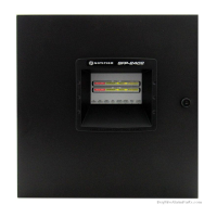
ID50 Series Panel - Installation, Commissioning & Configuration Manual
Configuration Mode
37
997-263-000-11, Issue 11
January 2010
5 Configuration
5.1 Introduction
The following sections contain instructions to configure
a panel.
For each configuration option, a brief description of its
purpose is given, followed by the configuration procedure
accompanied by illustrations of appropriate LCD displays.
The panels use menu-driven software which is divided
into Level 2 Configuration Options (see Section 5.3) and
Level 3 Configuration Options (see Sections 5.4 - 5.11).
5.2 Navigation and Number Entry
To navigate around the menus and enter numeric values,
refer to the ID50 Series Operating Manual 997-264-000-X,
Section 4.6.
5.3 Level 2 Configuration Options
The Level 2 Configuration Options are described in the
ID50 Series Panel Operating Manual 997-264-000-X.
The applicable sections are listed below:
a. Test - Section 4.9
b. Disable/Enable - Section 4.10
c. Clock - Section 4.11
d. View Mode
1
- Section 4.12
e. Commissioning - Section 4.13
f. Print - Section 4.14
1
With ID60 panels there is a View Mode menu option
for displaying VIEW, Optiplex and SMART 4 sensor
maintenance log data (Access Level 3 required).
The Operating Manual also includes a Level 2 menu
map.
For the default Level 2 passcode refer to Appendix 1 -
Specifications.

 Loading...


