ID50 Series Panel - Installation, Commissioning & Configuration Manual
Installation Guide
14997-263-000-11, Issue 11
January 2010
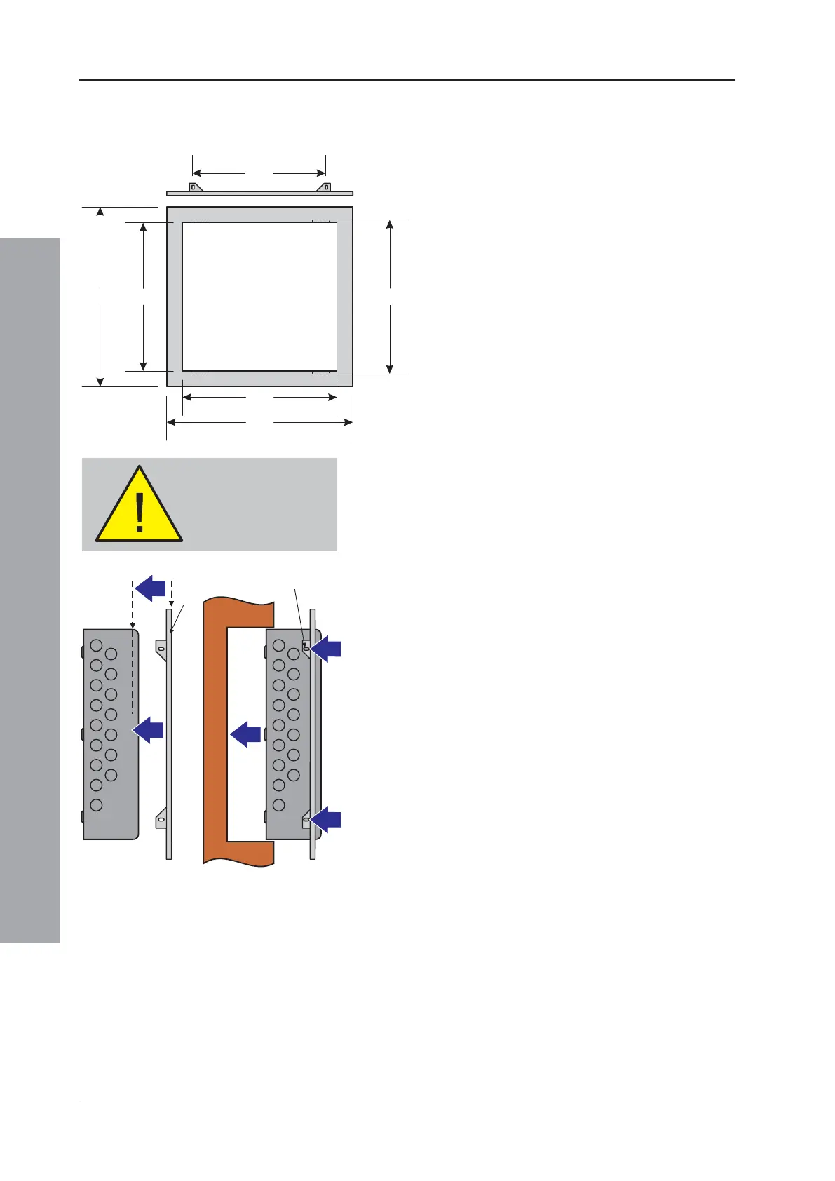
2.5.4 Semi-Flush Mounting Bezel (Optional)
If semi-flush mounting of the ID50 Series Panel is
required, a recess 80mm deep and just large enough to
accommodate the back box must be cut in the wall (see
dimensions below).
All dimensions in millimetres
To fit the bezel:
1 Before continuing, remove panel electronics and
batteries (if fitted) - see Section 2.5, Dismantling the
Panel.
2 Offer the bezel (A), flat sideways towards you, to the
front of the back box (B) and position it so the bezel
front face (C) is lined up with the rear of the rounded
sides of the back box (D).
3 With the bezel held in position, use the slotted holes
(E) on the bezel as guides and drill four appropriate
sized holes to fit M3 screws centrally in the slots.
Remove any swarf created.
4 Secure the bezel using suitable M3 fixings. Ensure
the fixings are accessible from the outside of the back
box.
Note: The ID50 Series Panel back box must be fixed to
a solid vertical surface, or sub-frame inside the
recess, using its rear fixing holes. Do NOT rely on
the bezel as a means of fixing.
5 Fit back box with attached bezel to the wall recess
and assemble the panel, see Section 2.6.
Before drilling the back
box, make sure that no
equipment is fitted
WALL
RECESS
E (x4)

 Loading...


