ID50 Series Panel - Installation, Commissioning & Configuration Manual
Configuration Mode
79 997-263-000-11, Issue 11
January 2010
5.6.3 On-Board Circuits
This option permits configuration of the On-Board Output
Circuits. There are six output circuits as defined in the
following table:
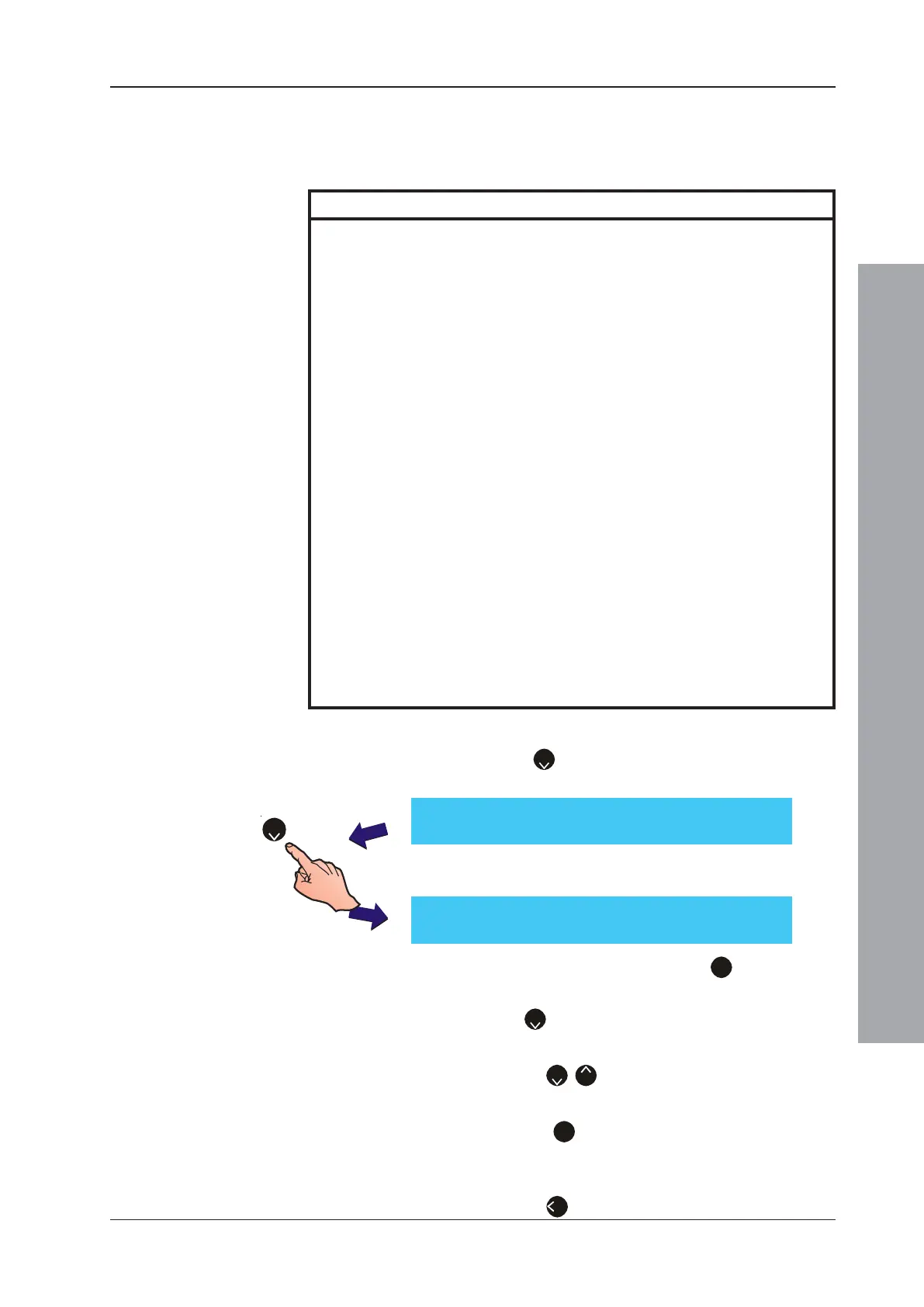
To change the On-Board Output CBE rule:
1 Press ‘
2
’ on the numeric keypad, select the
On-Board menu from the Circuit Menu below.
2 The display then shows the following menu. Select
the appropriate action:
a. Using the numeric keypad press ‘
1
’ to change the
Type of output, or
b. Press ‘
2
’ on the numeric keypad to change the CBE
Rule with which the On-board output is associated.
c. Use the ‘
2
/
8
’ to change the On-board output
number and its associated CBE Rule.
d. Press the ‘
3
’ on the numeric keypad to toggle the
monitoring end-of-line device type: resistor (default
setting) or diode.
e. Press the ‘
4
’ to Cancel and return to the Circuit menu.
Output No. Type Description
1 (B01) Fixed Monitored Monitored Sounder (SDR or SDH) or Monitored Control
Output Circuit (A) Module (CTL) or Transmission Device (TxD) can be
programmed for Fire Alarm, Fault, Pre-Alarm, Plant
Warning or Extinguishing System CBE Rules.
Factory Default = Fire Alarm - All Zones.
2 (B02) Fixed Monitored Monitored Sounder (SDR or SDH) or Monitored Control
Output Circuit (B) Module (CTL) can be programmed for Fire Alarm, Fault,
Pre-Alarm, Plant Warning or Extinguishing System CBE
Rules.
Factory Default = Fire Alarm - All Zones.
3 (B03) Hardware Configurable Can be configured for operation as a Monitored Output
CFG Output Circuit (C) (Sounder Circuit or Relay Circuit) or as an Unmonitored
Output (volt-free style relay Circuit).
Can be programmed for Fire Alarm, Fault, Pre-Alarm,
Plant Warning or Extinguishing System CBE Rules.
Factory Default = Unmonitored Relay.
4 (B04) Hardware Configurable Can be configured for operation as a Monitored Output
CFG Output Circuit (D) (Sounder Circuit or Relay Circuit) or as an Unmonitored
Output (dry-contact style relay Circuit).
Can be programmed for Fire Alarm, Fault, Pre-Alarm,
Plant Warning or Extinguishing System CBE Rules.
Factory Default = Unmonitored Relay.
5 (B05) -VE Output Circuit (1) Unmonitored Output Circuit. Can be programmed for Fire
Alarm, Fault, Pre-Alarm, Plant Warning or Extinguishing
System CBE Rules.
This output is normally used to drive an external relay.
Factory Default = General Pre-Alarm
6 (B06) -VE Output Circuit (2) Unmonitored Output Circuit. Can be programmed for Fire
Alarm, Fault, Pre-Alarm, Plant Warning or Extinguishing
System CBE Rules.
This output is normally used to drive an external relay.
Factory Default = Plant Warning
[S1 Circuit] 1 : SLC Loop 2 : On-Board
[ON-BOARD] B01 (SDR) 3: Mon. : RES.
1 : Type 2 : CBE Rule (01) ¦ : Change < : Exit
2

 Loading...


