ID50 Series Panel - Installation, Commissioning & Configuration Manual
Commissioning
25 997-263-000-11, Issue 11
January 2010
EN54-2 : 8.2.4c.
Earth Fault Monitoring
is required.
ENABLEDDISABLED
J19
J19
Earth Fault Monitoring (J19)
Earth fault monitoring should be enabled during normal
operation; this is the default condition and is indicated by
a fitted jumper link on J19 to the right of the CFG Outputs
C and D terminal block (TB3). To disable the earth fault
monitoring, remove the link.
The presence of an earth fault is indicated by a yellow
Earth Fault and general Fault LED.
Warning: If an earth fault already exists, DO NOT attempt
to connect additional equipment likely to cause
earth faults as damage may result, i.e. inhibiting
the monitoring will not protect the equipment.
Note: Direct connection of a VDU etc. to the RS232 serial
port D-type plug connector PL5, will result in an
earth fault and potential damage to the connecting
equipment. This fault can be removed by use of
an isolated RS232 link or by (temporarily) disabling
the earth leakage detection. Wait at least one
minute after disabling the earth fault monitoring
circuit before plugging into PL5.
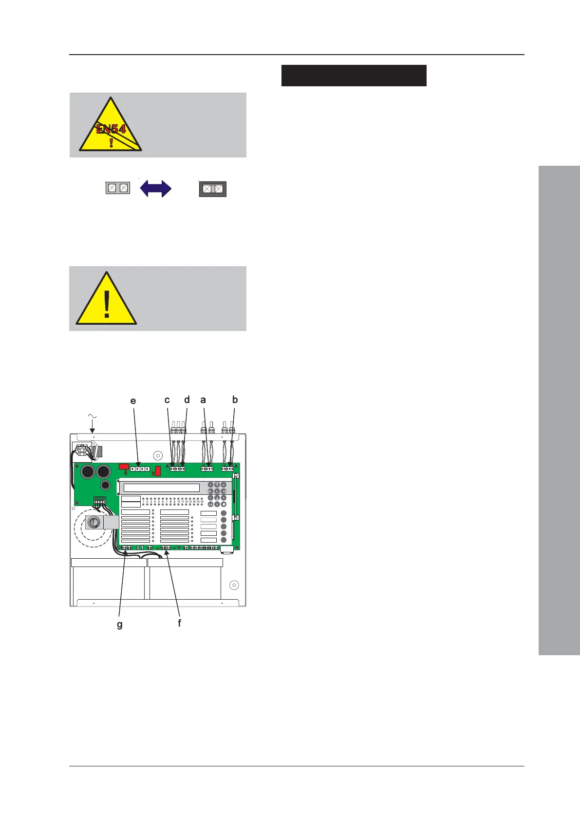
4.4 External Wiring Checks
The following sections describe the procedures for
checking and connecting the external wiring:
a. See Section 4.4.1, Loop Wiring*,
b. See Section 4.4.2, RS485 Communications Link,
c. See Section 4.4.3, DC Auxiliary Output,
d. See Section 4.4.4, Sounder Circuit Outputs A and B,
e. See Section 4.4.5, CFG Outputs C and D,
f. See Section 4.4.6, -VE Outputs, and
g. See Section 4.4.7, Digital / ÜE Inputs.
DO NOT remove link if
there is an existing earth
fault. If link is removed,
ensure it is fitted before
replacing front cover.
* Notifier has a PC-based Loop Diagnostic Tool (LDT).
This tool is easy to use and its purpose is to reduce
the amount time spent resolving cable and wiring
termination faults. Contact Notifier Technical Support
for details.

 Loading...


