ID50 Series Panel - Installation, Commissioning & Configuration Manual
Commissioning
30997-263-000-11, Issue 11
January 2010
4.4.5 CFG Outputs C and D
CFG Outputs C and D can be configured as sounder or
relay output circuits using configurable jumper links.
Output C is configured using jumper link J1 and Output
D is configured using jumper link J2.
The link settings for J1 and J2 are defined in the table
below. These changes must only be made with the system
powered down and become effective automatically on
power-up.
CFG Outputs C and D can be connected as:
a. Monitored Sounder Circuits, or
b. Un-monitored Relay Outputs
Note: A sounder output can be used to drive an external
relay to provide a monitored relay output.
Before connecting CFG Outputs C and D to the PCB
assembly, the appropriate hardware links may need to
be set.
CFG Fit Jumper Sounder/ For For
OUTPUT Links Over: Remote Unmonitored Unmonitored
Relay Normally-Open Normally-Closed
Output C J1 1 & 3 1 & 2 1 & 2
(default un- 4 & 6 3 & 5 5 & 6
monitored NC) 5 & 7 7 & 8 7 & 8
Output D J2 1 & 3 1 & 2 1 & 2
(default un- 4 & 6 3 & 5 5 & 6
monitored NO) 5 & 7 7 & 8 7 & 8
Fault Relay - In the panel’s quiescent state a relay
configured as a fault relay is energised. Make the
appropriate ‘+’ and ‘-’ wiring connections.
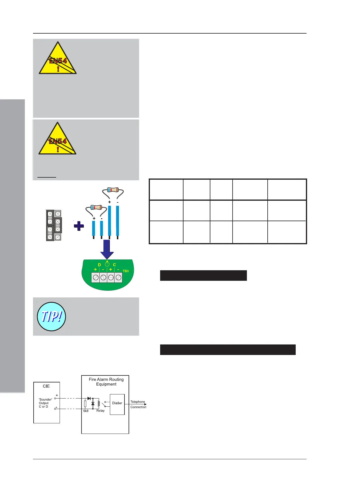
Sounder Circuits
If these connections are to be configured as sounder
circuits make sure:
a. The 6k8 end-of-line resistors
1
are correctly connected
to the end of the circuit, and
b. Correct polarity is used when terminating at the back
box, i.e. terminal 1 being positive and terminal 2 being
negative.
Monitored Remote Relay /Fire Routing Outputs
If these connections are to be configured to monitor for
open and short circuits make sure:
a. The 6k8 end-of-line resistors
1
are connected correctly
to the end of the circuit, and
b. Correct polarity is used when terminating at the back
box, i.e. terminal 1 is positive and terminal 2 is negative.
c. A blocking diode is connected in series with the relay coil.
d. A back-emf diode should be connected across the
relay coil.
1
J1 & J2
3
5
7
2
4
6
8
CFG Outputs C and D have
a default configuration of
unmonitored relay outputs
(see next page).
1
Alternatively, for partial-open- and partial-short-circuit
monitoring use one of the diodes supplied with each sounder
circuit in place of the 6k8 resistor.
EN 54-2 : 7.7.1
One output must be
configured as a fire
output.
EN 54-2 : 7.8
If an EN54-2 monitored sounder
output is required an unmonitored
relay is not suitable. Use a
monitored sounder output.
EN 54-2 : 8.8
Either a relay
1
or a
sounder output
1
may be
configured as a fault
output.
1
These outputs are not monitored and
they should not be used as a fault
routing output (EN 54-2: 8.9).

 Loading...


