ID50 Series Panel - Installation, Commissioning & Configuration Manual
Installation Guide
18997-263-000-11, Issue 11
January 2010
RS232
FIRE
DISABLEMENT
ID50 FIRE CONTROL PANEL
Complies with EN54-2/4 1997
Period of Manufacture 1999
FAULT
RESET
EXTEND DELAY
TEST
POWER SUPPLY FAULT
EARTH FAULT
POWER
PLANT ALARM
FIRE OUTPUT ACTIVE
DELAYS ACTIVE
FIRE OUTPUT: FAULT / DISABLED
FIRE CONTROL O/P: FAULT/ DISABLED
PRE- ALARM
SYSTEM FAULT
SOUNDER: FAULT/ DISABLED
MUTE BUZZER
SILENCE/
RESOUND
END DELAY/
EVACUATE
12
3
4
56
7
8910
11 12
13
14
15 16
ZONE FIRE
ZONE FAULT
DISABLE/TEST
00..9
31
2
46
7
5
[
98
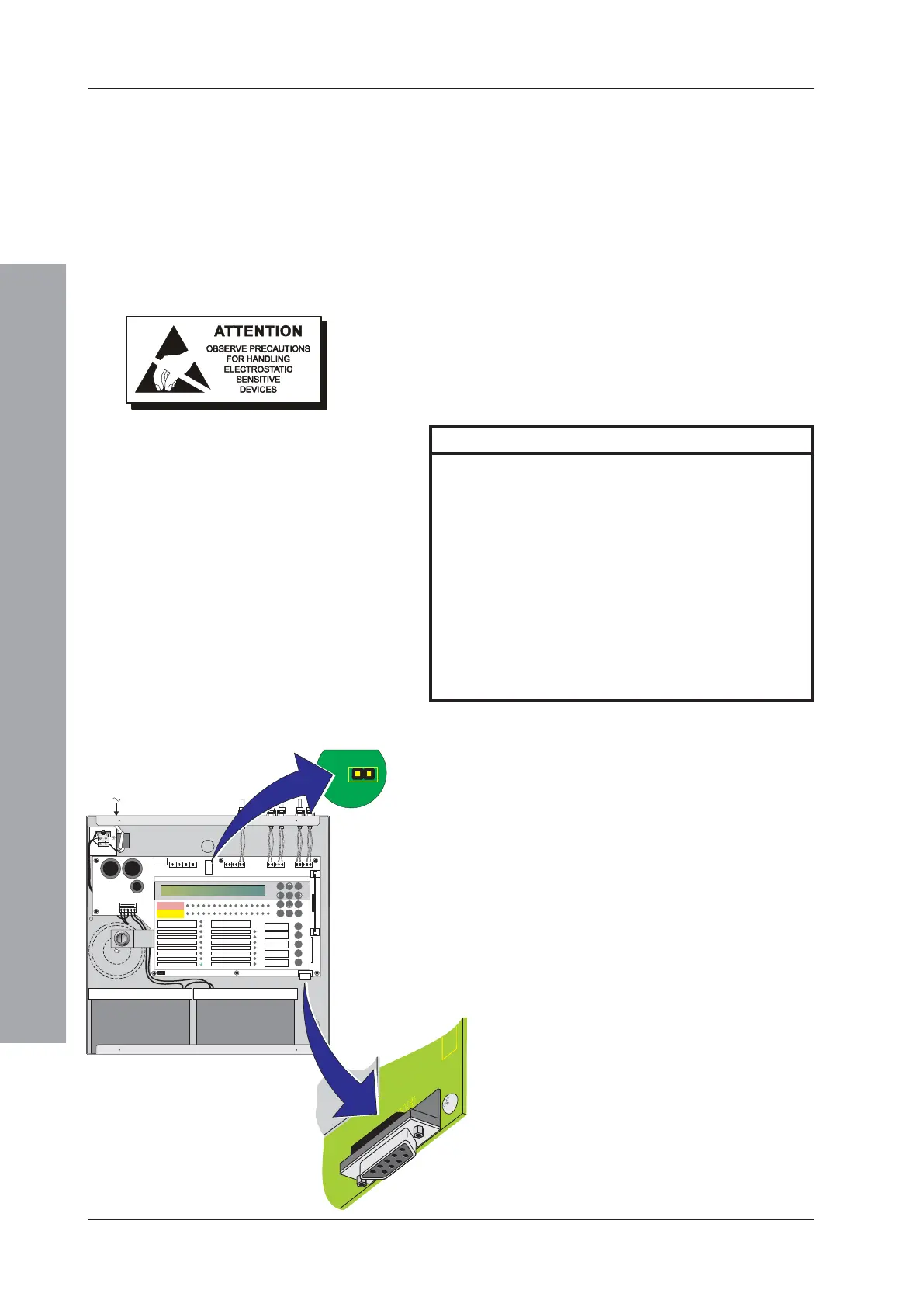
2.8 RS232 Interface Connections
The panel is fitted with a standard 9-way ‘D’-type RS232
Interface connector, located at the bottom right-hand
corner of the PCB assembly. The RS232 connector is
used for the following purposes:
a. Configuration using the PC Support Tool (refer to
997-405, ID50 Series Panel - Offline Configuration
Manual).
b. Upgrading the Panel Software (refer to 997-415, ID50
Series Panel - Upgrading Instructions).
Before starting any of the above operations ensure
suitable anti-static precautions have been taken.
The RS232 connector has the following pin out:
Pin Description
1 Data Carrier Detect (DCD)
2 Receive (RX) Data *
3 Transmit (TX) Data *
4 Data Terminal Ready (DTR)
5 GND *
6 Data Set Ready (DSR)
7 Request To Send (RTS)
8 Clear To Send (CTS)
9 Not Applicable
Note: Pin numbers marked thus ‘*’ are the only
required connections. Any others fitted will
be ignored.
A Data Transfer Lead (PN: 082-173) is required. Jumpers
must be removed as follows:
1 Remove the cover (refer to Section 2.5.1, Removing
the cover) to access the panel electronics.
2 Remove the Jumper Links J19 (earth fault monitoring)
and J9 (configuration memory lock).
Note: Refer to Section 4.3.1 Jumper Link Options/
Earth Fault Monitoring (J19) when connecting
third-party equipment to the panel.
3 Fit the Data Transfer Lead to the RS232 Interface
connector, PL5.
4 Perform required operation.
5 After satisfactory completion disconnect the lead and
then fit the jumpers.

 Loading...


