ID50 Series Panel - Installation, Commissioning & Configuration Manual
Installation Guide - Cabling
21 997-263-000-11, Issue 11
January 2010
3.2 Cabling Installation Notes
3.2.1 Introduction
The following notes are intended to assist installers of
analogue addressable control systems. They have been
produced from information derived from the supplier’s
technical resource and from information fed back
concerning existing systems.
3.2.2 Quality of Cable and of Cable Installation
It is vitally important that good quality cable is used, and
that correct installation techniques are followed. In general,
the following cable installation requirements must be met:
a. All cable sections must be circular to allow effective
cable clamping using the cable glands.
b. The cable must be screened (sheathed) to provide
protection against Radio Frequency Interference (RFI)
and the screen must be connected to earth at the
control panel.
c. Multiple earthing of the screen should be avoided.
NOTIFIER’s field products use insulated mounting
bases and back boxes to achieve this. We recommend
that this practice be continued if other connections are
made. To achieve this with MICC cable may require
the use of insulated cable glands at one end of the cable.
d. The screen must be continuous throughout the loop.
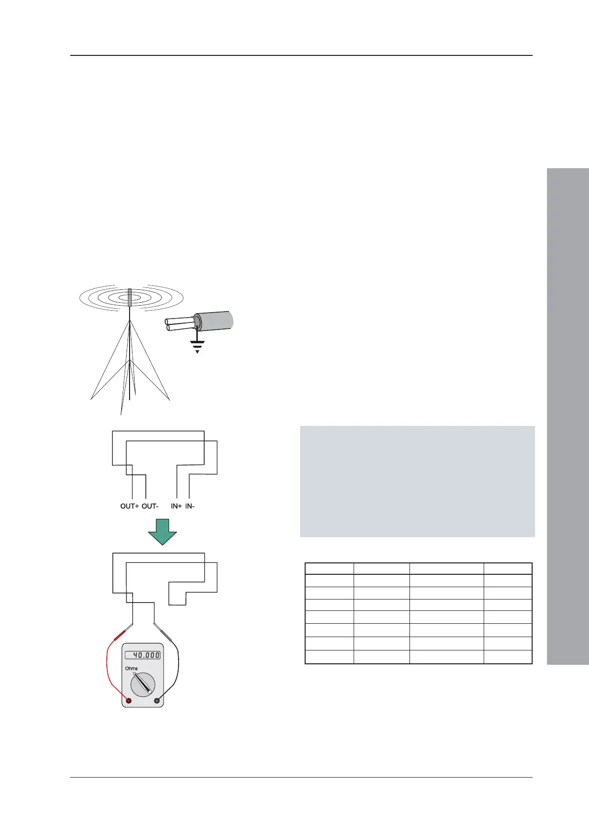
e. The maximum resistance of the loop should not
exceed 40 ohms. You may check this by joining the
return legs IN+ and IN- together and measuring across
the start legs OUT+ to OUT-. Also the cable
capacitance should be less than 0.5μF. Typically this
will allow a maximum loop length of 2000m of screened
1.5mm
2
cable. Cable recommended for use is MICC
with a LSF PVC overcovering, a fire-resilient cable to
BS7629 or PVC/SWA/PVC to BS6387.
Recommended Cables:
Manufacturer Product Name Part Number Type
1
AEI MICC 2L1.5 Enhanced
AEI Firetech 298-052 Standard
Draka FiretufPlus FTPLUS2E1.5RD Enhanced
Draka Firetuf FTZ2E1.5 Standard
Pirelli FP Plus FP Plus 2x1.5 Red Enhanced
Pirelli FP200 Gold FP200 Gold 2x1.5 Red Standard
Arrow - 7-2-4S Not rated
1
For a definition of ‘Standard’ and ‘Enhanced’ cable requirements and their different
applications, refer to BS 5839-1 Section 26. Enhanced cable is typically required
for spur sounder outputs, while standard cables may be adequate for other fire-
related I/O provided there is diverse cable routing. The multi-core cable from Arrow
is suitable for RS232 connections to a printer.
f. We recommend that the system should be wired in
2-core cables and each 2-core cable should be specific
to one function.
g. The RS485 communication cable used should be rated
as suitable for up to 200mA in a short circuit condition.

 Loading...


