ID50 Series Panel - Installation, Commissioning & Configuration Manual
Commissioning
33 997-263-000-11, Issue 11
January 2010
12
3
4
56
7
8910
11 1 2
13
14
15 16
ZONE FIRE
ZONE FAULT
DISABLE/TEST
00..9
31
2
46
7
5
[
98
MUTE BUZZER
RESET
EXTEND DELAY
END DELAY/
EVACUATE
SILENCE/
RESOUND
FIRE
DISABLEMENT
FAULT
TEST
POWER SUPPLY FAULT
EARTH FAULT
POWER
PLANT ALARM
FIRE OUTPUT ACTIVE
DELAYSACTIVE
FIRE OUTPUT:FAULT / DISABLED
FIRE CONTROL O/P: FAULT/ DISABLED
PRE- ALARM
SYSTEM FAULT
SOUNDER: FAULT/ DISABLED
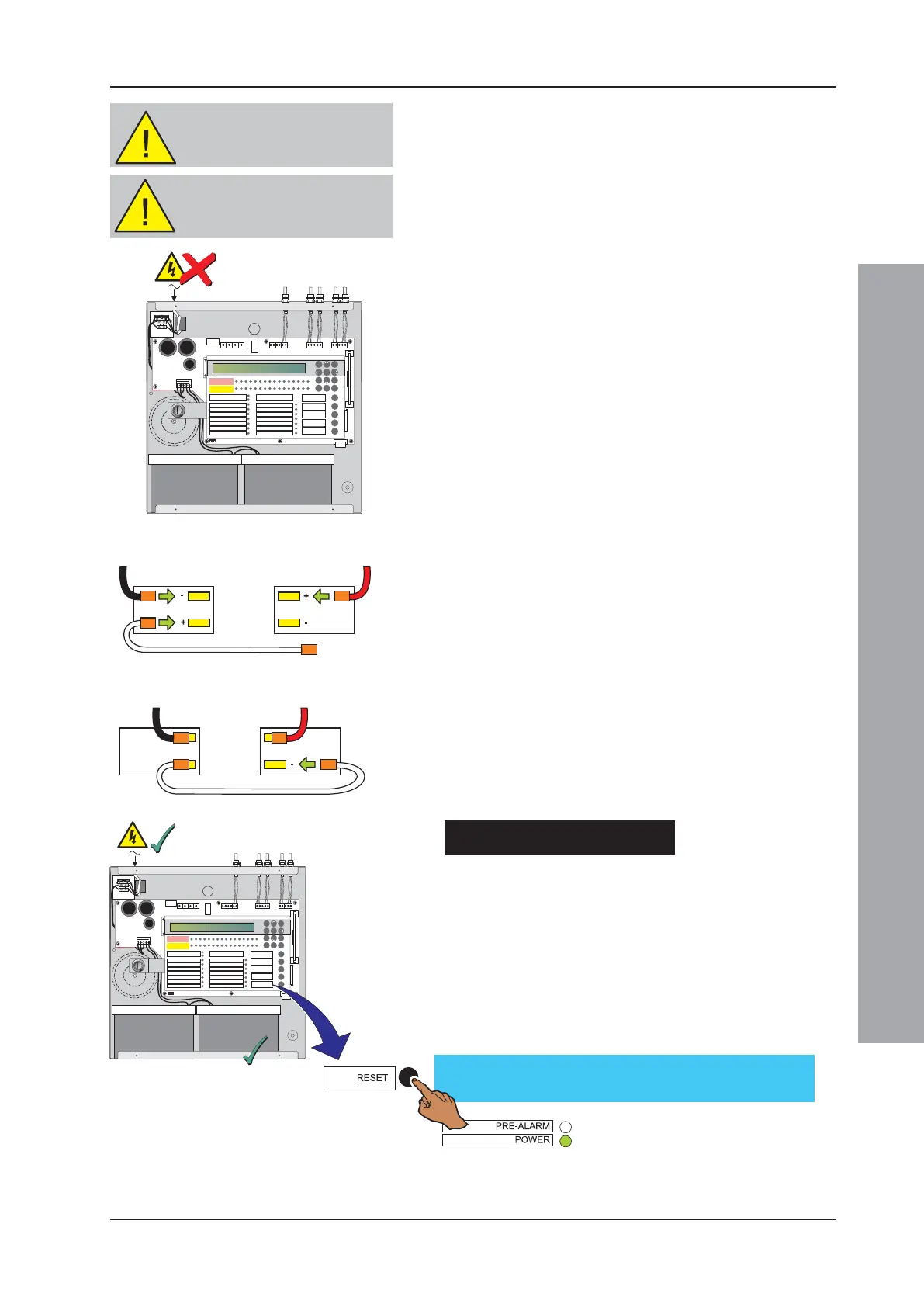
4.5.2 Batteries
The ID50 Series Panel back box holds up to two 12V,
12Ah batteries. The batteries are not supplied with the
panel. A valve-regulated, lead-acid type MUST be used.
To avoid contact damage resulting from repeated
connection point arcing, it is recommended that the mains
is connected before the batteries.
To connect the batteries:
1 Externally isolate the mains supply at the third-party-
supplied isolation unit, remove the cover and fit the
batteries in the back box. If not done already, connect
the mains/battery/ supply wiring plug to the power
socket, between the transformer secondary fuse (FT1)
and the battery fuse (FC1).
2 Connect the red wire from the terminal block, TB2
(BAT+) to the positive terminal of battery 2 and the
black wire from the terminal block, TB2 (0V) to the
negative terminal on battery 1.
Connect one end of the interlink cable to battery 1
positive terminal only. DO NOT connect both ends of
the interlink cable at this stage.
3 Turn on the AC mains supply and verify that after
power-up:
i The panel indicates ‘CPU RESTART’.
ii The buzzer sounds.
iii The FAULT and SYSTEM FAULT LEDs illuminate.
4 Connect the interlink cable to the negative terminal
on battery 2.
5 Reset the panel and check that the LCD displays the
‘Status: NORMAL’ message and that the FAULT and
SYSTEM FAULT LEDs extinguish.
Battery Disposal
As a minimum, replace the batteries every four years.
Always dispose of the batteries in accordance with the
battery manufacturer’s recommendations and local
regulations.
Status: NORMAL
Sat 05/01/2002 00:00:00
CAUTION- ENERGY HAZARD!
NEVER short the battery
terminals.
2
4
5
TB2 (0 V)
Battery 1
TB2 (BAT +)
Battery 2
Battery
1
Battery
2
12
3
4
56
7
8910
11 12
13
14
15 16
ZONE FIRE
ZONE FAULT
DISABLE/TEST
00..9
31
2
46
7
5
[
98
MUTE BUZZER
RESET
EXTEND
DELAY
END DELAY/
EVACUATE
SILENCE/
RESOUND
FIRE
DISABLEMENT
FAULT
TEST
POWER SUPPLY FAULT
EARTH FAULT
POWER
PLANT ALARM
FIRE OUTPUT ACTIVE
DELAYSACTIVE
FIRE OUTPUT: FAULT / DISABLED
FIRE CONTROL O/P: FAULT/ DISABLED
PRE- ALARM
SYSTEM FAULT
SOUNDER: FAULT/ DISABLED
CAUTION- RISK OF EXPLOSION!
If battery is replaced with an
incorrect type.

 Loading...


