ID50 Series Panel - Installation, Commissioning & Configuration Manual
Installation Guide
16997-263-000-11, Issue 11
January 2010
2.7 RS485 Communications Link
The panel is capable of communicating with a maximum
of sixteen (16) repeaters (active IDR-2A or passive
IDR-2P) or mimic panels (IDR-M) (for further details
concerning the repeaters refer to 997-411, IDR-2A, -2P
& -6A Repeaters User Manual or 997-412, IDR Mimic
Installation and Commissioning Manual). The panel
is connected to the repeaters in a ‘daisy-chain’
arrangement via the RS485 Communications terminal
block, TB6, on the PCB assembly. The panel must be
fitted with the RS485 Interface Module PCB at connector
PL3 on the PCB assembly (see Section 2.7.1, Fitting
the RS485 Interface Module PCB).
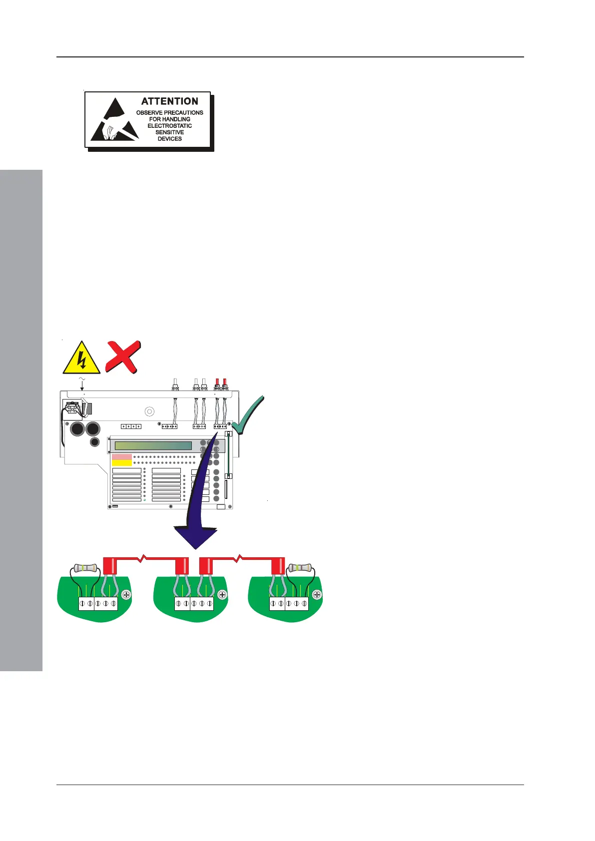
The two end stations require a termination resistor to be
fitted as illustrated below.
To connect a panel to an RS485 communications link:
1 Ensure the following:
i All power to the panel is isolated.
ii Access to the panel electronics is possible.
ii The interlink wire is disconnected at the batteries.
2 Fit the RS485 Interface Module PCB as described in
the instructions in Section 2.7.1, Fitting the RS485
Interface Module PCB).
3 Connect the RS485 communications cable to the
RS485 Communications terminal block, TB6, refer
to Section 4.4.2, RS485 Communications Link.
Note: If connecting the panel at either end of the RS485
communications link, connect a 150R termination
resistor (supplied separately) as shown below.
4 Using the configuration procedure - refer to
Section 5.5.4.6, Number of Repeaters, configure the
panel and RS485 communications link.
If Fitted As First
Station On RS485
Comms Link
Intermediate
Station(s)
If Fitted As Last
Station On RS485
Comms Link
RS485
B A B A
RS485
B A B A
RS485
B A B A
TB6
TB6
TB6
FIRE
DISABLEMENT
ID50 FIRE CONTROL PANEL
Complies with EN54-2/4 1997
Period of Manufacture 1999
FAULT
RESET
EXTEND DELAY
TEST
POWER SUPPLY FAULT
EARTH FAULT
POWER
PLANT ALARM
FIRE OUTPUT ACTIVE
DELAYS ACTIVE
FIRE OUTPUT: FAULT / DISABLED
FIRE CONTROL O/P: FAULT/ DISABLED
PRE- ALARM
SYSTEM FAULT
SOUNDER: FAULT / DISABLED
MUTE BUZZER
SILENCE/
RESOUND
END DELAY/
EVACUATE
12
3
4
56
7
8910
11 12
13
14
15 16
ZONE FIRE
ZONE FAULT
DISABLE/TEST
00..9
31
2
46
7
5
[
98

 Loading...


