ID50 Series Panel - Installation, Commissioning & Configuration Manual
Commissioning
28997-263-000-11, Issue 11
January 2010
4.4.4 Sounder Circuit Outputs
The sounder cicuits are designed to work either with a
resistor end-of-line (EOL) device (default) or, to comply with
the requirements for partial shorts and open monitoring
of EN54-13 (Compatibility Assessment of System
Components), where a diode EOL device is required. If
resistor EOL devices are to be used follow the first procedure
described below. If diode EOL devices are to be used refer
to the procedure described overleaf.
4.4.4.1 Using Resistor EOL Devices
Before the sounder circuits are connected it is
recommended that all detection circuits have been
checked and that there is no possibility of spurious alarm
conditions being generated. The sounders should be
polarized and suppressed using IN4002 (or similar)
diodes and the circuits should be fitted with 6k8 end-of-
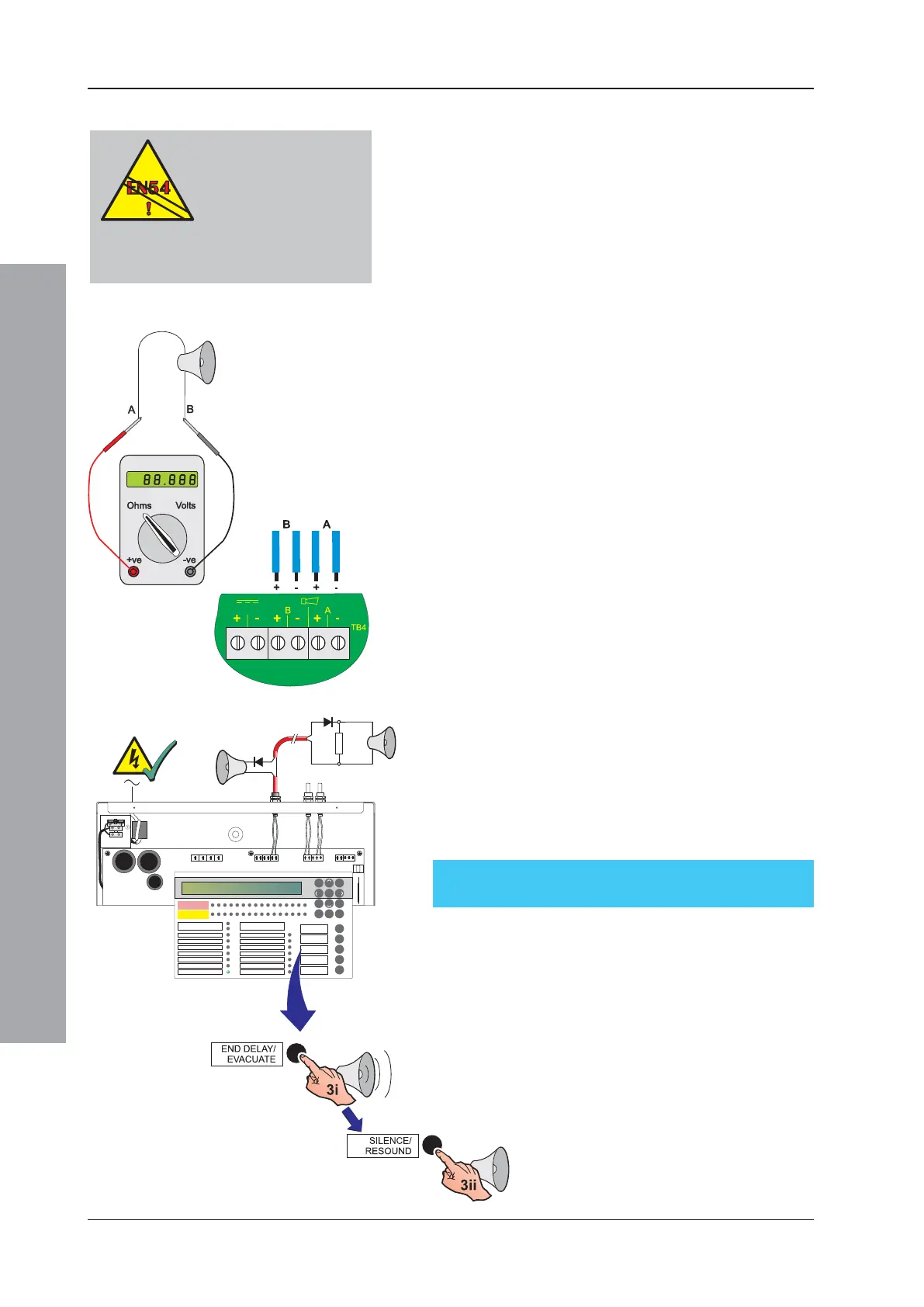
line resistors. Perform the following checks:
1 Use a low-voltage multimeter to check the resistance
across each of the sounder circuits:
i With the meter connected in reverse polarity (+ve
to -ve and -ve to +ve) the reading should be 6k8.
ii With the multimeter connected to the circuit in
normal polarity (+ve to +ve and -ve to -ve) the meter
may indicate a lower value. This is because of the
forward-biased diodes in series with the sounders.
2 If electronic sounders are used this test will not reveal
reversed devices. It is, therefore, recommended that
if the circuit resistance appears correct, the following
be done:
i Remove the 6k8 resistors from the panel outputs.
ii Connect the circuit to the panel output while
observing correct polarity.
iii If there are any reversed devices the panel will then
indicate:
‘Sounder cct. n SHORT-CCT.’.
3 When the output circuits have been connected, they
may be tested using the ‘END DELAY / EVACUATE’
pushbutton.
i Press the ‘END DELAY / EVACUATE’ pushbutton
to activate the Output circuits.
ii Press the ‘SILENCE/RESOUND’ pushbutton to
silence all activated output circuits.
iii If the outputs operated correctly press the ‘RESET’
pushbutton. If not, check all possible causes and
correct any faults that exist, then repeat Step 3.
FIRE
DISABLEMENT
ID50 FIRE CONTROL PANEL
Complies with EN54-2/4 1997
Period of Manufacture 1999
FAULT
RESET
EXTEND DELAY
TEST
POWER SUPPLY FAULT
EARTH FAULT
POWER
PLANT ALARM
FIRE OUTPUT ACTIVE
DELAYS ACTIVE
FIRE OUTPUT: FAULT / DISABLED
FIRE CONTROL O/P: FAULT/ DISABLED
PRE- ALARM
SYSTEM FAULT
SOUNDER: FAULT / DISABLED
MUTE BUZZER
SILENCE/
RESOUND
END DELAY/
EVACUATE
12
3
4
56
7
8910
11 12
13
14
15 16
ZONE FIRE
ZONE FAULT
DISABLE/TEST
00..9
31
2
46
7
5
[
98
EN 54-2 : 7.8
If an EN54-2 monitored
fire alarm routing
output is required an
unmonitored relay is
not suitable - use a monitored routing
output.

 Loading...


