Technical Specifications
MAN0984_Iss 4_01/19 Touchpoint Plus
Pt. No. 3011M5001 124 Technical Handbook
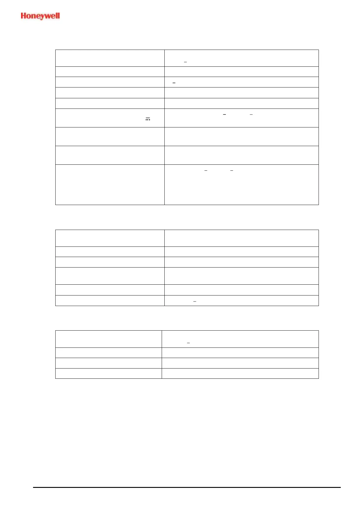
11.3 I/O Modules
11.3.1 mA Input Module
2,4 and 8-channel Analogue Input Module for 2-wire or 3-
wire 4 20 mA detector signals
2-wire or 3-wire current source
Max 0.3 W (Excludes power to field device)
Field Device Power Supply Vmax ( )
Supply voltage Vs (18 32 VDC) *1.8 VDC (max)
*Voltage drop in Touchpoint Plus
Field Device Power Supply Power max
(single channel)
Field Device Power Supply Power max
(eight channels)
40 W (Maximum for eight channel per a module)
Maximum cable length for mA Input
loop (R
loop
)
R
loop
= (V
controller
1.8 VDC V
detector
min) / I
detector
Maximum Cable run length = R
loop
/ (Ω per metre).
Example: V
controller
= 24 VDC, TPP Voltage drop = 1.8 VDC,
V
detector
= 18 VDC (18 to 32 VDC), I
detector
= From detector
specification.
11.3.2 mV Input Module
2,4 and 8-channel Analogue Input Module for mV-Bridge
signals
Current Range for sensor (Fixed)
Maximum Power Consumption
18.5 W (including power to detector @ loop resistance of
36 Ω)
36 Ω at 200 mA (including sensor)
11.3.3 Dual Input Module
2/2 and 4/4-channel Analogue Input Module for 2-wire or
3-wire 4 20 mA detector signals and mV-Bridge signals
Refer to Ch.11.3.1 mA Input Module
mA Field Device Power Supply Power
20 W max. (Four channels)
Refer to Ch.11.3.2 mV Input Module

 Loading...


