Electrical Power Connection and Interfacing
MAN0984_Iss 4_01/19 Touchpoint Plus
Pt. No. 3011M5001 36 Technical Handbook
Note 1: +24 VDC Nominal = Controller Input (18 to 32 VDC) 1.8 VDC (the max voltage drop in the TPPL).
Note 2: Alarm Terminals 13, 19, 20, and 21 can supply +24 VDC at 28 W combined this 28 W can instead be used to
increase the power available to field sensors if external audible and visible alarms are not connected. e.g. the 8 sensor
channels would normally have W of combined available power, but this can be increased to 68.8 W if terminals 13
21 are unused.
Note 3: You must supply sensors with external power if more than 40 / 68 W total power is required (See Note 2).
Note 4: Maximum R
loop
resistance for a remote reset/inhibit switch is 18 Ω, for instance m of 1 mm
2
shielded
cable.
Note 5: RLY1 or RLY2 should be configured as "system inhibit relay"
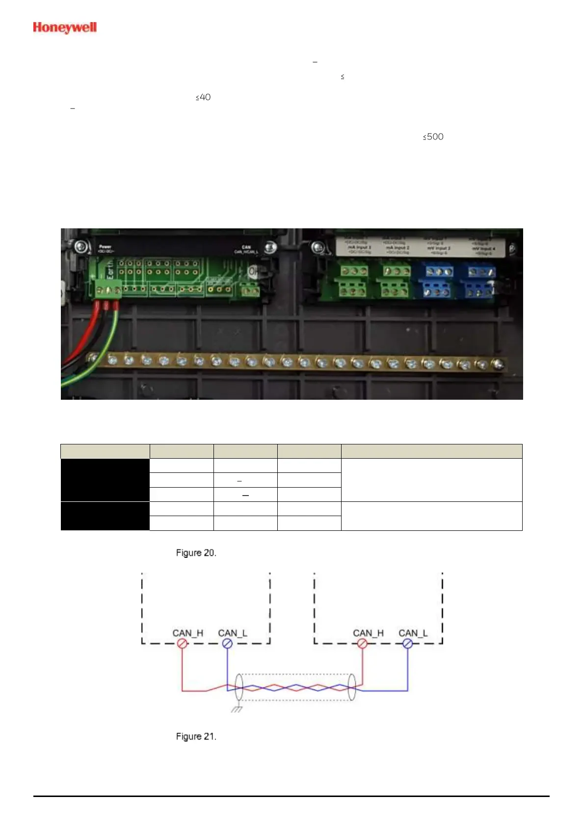
5.2.6 Expansion Module Power Connections
The cables must be fitted through a gland to preserve the IP rating.

 Loading...


