Home
Honeywell
Controller
Touchpoint Plus
Honeywell Touchpoint Plus Technical Handbook
5
of 1
of 1 rating
158 pages
Give review
Manual
Specs
To Next Page
To Next Page
To Previous Page
To Previous Page
Loading...
Electrical Power C
onnectio
n and Interfacing
MAN0984_Iss 4_01/
19
Touchpoint Plus
Pt. No. 3011M5001
39
Technical Hand
book
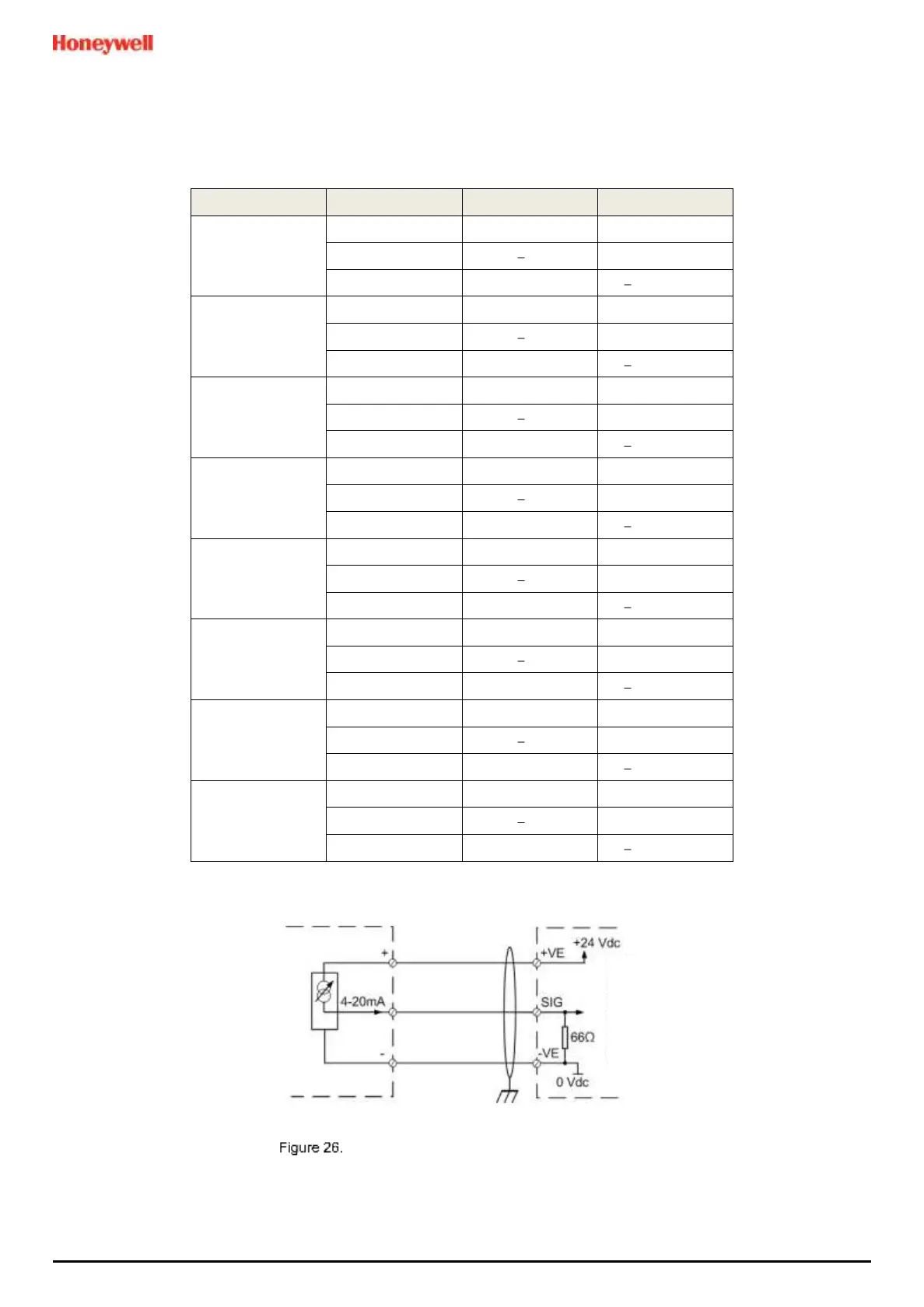
5.2.10
mA
Input Mod
ule Connecti
ons
Note:
mA
inp
ut channels are
limited
to
20
W per chann
el
to
a combined total
of
40
W
(68
W
if
Main Module Terminals
13
to
21
are not used). Sensors requiring
more
than
20
W must
have
their own power supplies.
Module Label
Terminal
Identifier
Field device
mA Input 1
1
+
VE
+24 VDC
2
VE
0 VDC
3
Sig
4
20 mA signal
mA Input 2
4
+
VE
+24 VDC
5
VE
0 VDC
6
Sig
4
20 mA signal
mA Input 3
7
+
VE
+24 VDC
8
VE
0 VDC
9
Sig
4
20 mA signal
mA Input 4
10
+
VE
+24 VDC
11
VE
0 VDC
12
Sig
4
20 mA signal
mA Input 5
13
+
VE
+24 VDC
14
VE
0 VDC
15
Sig
4
20 mA signal
mA Input 6
16
+
VE
+24 VDC
17
VE
0 VDC
18
Sig
4
20 mA signal
mA Input 7
19
+
VE
+24 VDC
20
VE
0 VDC
21
Sig
4
20 mA signal
mA Input 8
22
+
VE
+24 VDC
23
VE
0 VDC
24
Sig
4
20 mA signal
Table 6.
mA
Input Module Connections
Three Wire Device Powered
by
a
mA
Input Module
Touchpoint Plus
mA Input Module
Sensor
38
40
Table of Contents
Table of Contents
5
Chapter 1. Important Information
9
Regulatory Approval Markings
9
Additional Product Markings
9
TPPL Mandatory Warning
9
TPPL General Warnings
10
TPPL General Cautions
11
How to Use this Manual
11
Intended Readers
11
Conventions Used
11
Associated Manuals
12
Chapter 2. Safety Hazards, Warnings and Cautions
13
Safety
13
Warnings and Cautions
13
Safety Hazards
14
Location and Description of Warning Labels
16
Safety Warning Labels
16
Electrical Hazards
17
General Safety Precautions
17
Component Testing and Replacement
17
Good Practice
18
Lithium Battery Hazard
18
Product Compliance
19
Training of Personnel
20
Conditions Satisfying Local, National and International Safety Regulations
20
Approved Maintenance and Servicing Procedures
20
Security Guide
20
Firmware and EEPROM Update
20
Chapter 3. System General Description
21
How to Open and Close the Enclosure
23
Equipment Specification
24
Power Requirements (Controller Unit Only)
24
Maximum Power Consumption Calculations
24
Power Supply (SMPS RS 150 24) Electrical Ratings
24
Weights
25
Dimensions
25
Ambient Operating Temperature
25
Overall Ambient Operating Humidity
25
Storage Conditions (Without Batteries)
25
Storage Conditions (with Batteries)
25
IP Rating
25
Construction
25
System Weights
25
Touchpoint Plus Packaging
26
Packaging Components for Return to Manufacturer
26
Disposal (WEEE Directive)
26
TPPL Construction
26
TPPL Basic Control Unit
26
TPPL Expansion Unit
27
TPPL DIP Switches
27
Chapter 4. System Mechanical Installation
28
Wall Mounting Requirements
28
Chapter 5. Electrical Power Connection and Interfacing
30
Power Connection
30
AC Power Supply
31
Regional Power Cable Colours
31
DC Power Supply
32
Backup Battery Pack
32
Cabling and Connection Requirements
33
AC Mains Voltage Power Cables
33
DC Power Cables
33
Field Device Cables
33
Optional Expansion Unit Connection
34
Main Module Connections
35
Expansion Module Power Connections
36
TPPL DIP Switches
37
Ethernet Connection (Option)
37
Module / Field Device Connections
38
Ma Input Module Connections
39
MV Input Module Connections
42
MV Input Module Connections
43
Dual Input Module Connections
44
Ma Output Module Connections
45
Relay Output Module Connections
46
Modbus Remote Terminal Unit (RTU) and Transmission Control Protocol (TCP) Connections
47
Modbus Configuration
49
Chapter 6. Commissioning
50
Menu Structure
50
The Information Menu
50
Information Menu
50
The Configuration Menu
51
The Maintenance Menu
52
System Test Menu
52
First Time Switch on
53
Home Screen Menu Icons
53
Logging In/Out
54
How to Log in
54
How to Log out
54
Password Rules
54
How to Change a Password
55
Forgotten Passwords
55
Date, Time and Language Settings
56
How to Set or Change Date, Time and Language Settings
56
Service Contact Settings
56
Touch Panel Configuration
57
How to Change the Backlight Timeout and Brightness
57
How to Calibrate the Touch Panel
57
Latching Alarms
57
Remote Reset / Acknowledge / Inhibit Switch Options
60
Data Logging
60
To Set or Change Data Logging
60
TPPL TCP/IP Address
61
Network Settings for WEB and MODBUS TCP
61
Modbus RTU Settings
62
Commission Input / Output Modules
63
Channel Configuration
63
Introduction
63
Configuring a Channel (Ma Input and MV Input Channels)
64
Editing a Configured Channel
65
Editing Ma Input Channel Settings
65
Editing MV Input Channel Settings
69
Editing Relay Output Channel Settings
71
Editing Ma Output Channel Settings
73
Calibrating Input Channels
75
Adjusting the MV Sensor Baseline
75
Calibrating a MV Input Channel
75
Calibrating a Ma Input Channel
77
Backing up the Configuration Settings
79
How to Back up the Configuration
79
How to Restore the Configuration
80
Chapter 7. Touchpoint Plus User Guide
81
User Interface General
81
Touchscreen
82
Switching on and off
82
Menu Items and Access Levels
83
Navigation Active Access Level Icons
85
SD Card Usage
85
User / Component Matrix
85
Checking the Capacity of the SD Card
86
Inserting or Replacing SD Cards
86
Normal Operation (Safety Functions)
87
Operating Overview
88
Touchscreen
88
User Interface Screen
88
Navigating the Channel Detail Screens
90
Navigation Active Events and Filtering
91
Navigation Menu
92
Responding to Alarms
93
Remote Reset and Acknowledge Switches
93
View Active Alarms
93
Accept or Acknowledge an Active Alarm
93
Reset a Latched Alarm
94
Event Information
94
Viewing E V E N T Information
94
Accepting / Acknowledging Active Events
94
Resetting Latched Events
95
Inhibiting Channels
95
To Inhibit Input Channels
95
To Clear Inhibits
95
To Change Inhibit Timeouts
96
Viewing Input Channels and Input Details
96
Viewing Output Channels
98
Viewing T H E Trend Graph
99
Viewing and Exporting Event History
100
To View the Event History
100
To Export the Event History
100
Accessing the System Information and Service Contact Details
100
System State and System Failure Relays
100
Monitoring TPPL Via the Optional Web Interface
101
Web Interface Configuration
101
Web Interface Channel List View
102
Web Interface Channel Summary View
102
Web Interface Connection Failed Dialog
102
Web Interface Navigation
103
Web Interface Information Menu Showing Event History
103
Chapter 8. Routine Maintenance and Scheduled Testing
104
Routine Maintenance
104
Periodic Checks
104
Routine Testing
105
Exercising the Audio/Visual Alarms
105
Exercising the Relays
106
Checking the Ma Outputs
106
Calibrating MV Input Channels
107
Periodic Scheduled Testing
109
Introduction
109
Field Inputs Test
110
Cause and Effect Test
110
LCD, LED and Buzzer Test
111
Reaction and Response Time Test
111
Chapter 9. Repairs, Replacements and Upgrades
112
How to Decommission and Remove a Serviceable I/O Module
112
To Remove a Serviceable Module
112
How to Replace a Faulty I/O Module
113
To Replace a Faulty Module
113
How to Add a New I/O Module
114
To Add a New Module
114
How to Update the Sensor Catalogue
115
How to Backup / Restore the System Configuration
116
To Create a Backup File
116
To Restore the Configuration from a Backup File
117
How to Update Firmware
118
How to Check Firmware Compatibility
118
How to Update the Firmware
119
Back up Battery Maintenance
120
Recommended Backup Battery Maintenance
120
How to Replace the Backup Battery
120
Return to Factory Default Settings
121
To Reset the Touchpoint Plus to Its Factory Default Settings
121
Battery On/Off Switch and Battery Connector
121
Chapter 10. Troubleshooting
122
Calling for Technical Support
122
Chapter 11. Technical Specifications
123
Environmental
123
User Interface and Main Module
123
I/O Modules
124
Ma Input Module
124
MV Input Module
124
Dual Input Module
124
Ma Output Module
125
Relay Output Module
125
Expansion Module
125
Power Supplies
125
External Supplies
125
Backup Battery
126
Enclosures
126
Wall Mount Enclosure
126
Chapter 12. Certifications
127
EU Declaration of Conformity
127
National and International Certificates of Compliance
127
European Performance Approval (DEKRA Testing and Certification Gmbh) for Systems
128
Special Conditions for Use When Used for Measurement of Flammable Gases
128
Special Conditions for Use When Used for Measurement of Toxic Gases or Oxygen129
129
Special Conditions for Software Update
129
Chapter 13. Replacement Parts and Optional Extras
130
Spare Parts
130
Publications
131
Chapter 14. TPPL Configuration Code
133
TPPL Configuration P/N Code Chart (Example)
133
Chapter 15. Icon Glossary
134
Configuration Menu
134
Maintenance Menu
134
Chapter 16. Compatible Sensors
135
TPPL Gas Detectors
135
Chapter 17. Configurable Parameter Reference Guide
136
Chapter 18. Event Codes
147
Chapter 19. List of Figures
155
Ma Output Module Connections
155
List of Tables Chapter 20.
157
Chapter 20. List of Tables
157
Other manuals for Honeywell Touchpoint Plus
User Guide
70 pages
Quick Start Guide
2 pages
Safety Manual
8 pages
5
Based on 1 rating
Ask a question
Give review
Questions and Answers:
Need help?
Do you have a question about the Honeywell Touchpoint Plus and is the answer not in the manual?
Ask a question
Honeywell Touchpoint Plus Specifications
General
Brand
Honeywell
Model
Touchpoint Plus
Category
Controller
Language
English
Related product manuals
Honeywell THP9045A
16 pages
Honeywell T775B2040
56 pages
Honeywell T775M2048
56 pages
Honeywell T775M2030
56 pages
Honeywell T775B2016
56 pages
Honeywell T775M2014
56 pages
Honeywell T775R2027
56 pages
Honeywell T775U2016
40 pages
Honeywell T775M2006
56 pages
Honeywell T775B2032
56 pages
Honeywell T2798I2000
18 pages
Honeywell T775 Series
52 pages

 Loading...


