System Mechanical Installation
MAN0984_Iss 4_01/19 Touchpoint Plus
Pt. No. 3011M5001 28 Technical Handbook
Chapter 4.
The system can be directly wall-mounted or on an optional mounting fixture. Whichever method is chosen, the
mounting must be sound, secure, and capable of supporting the weight of the enclosure plus the weight of any
cables and glands.
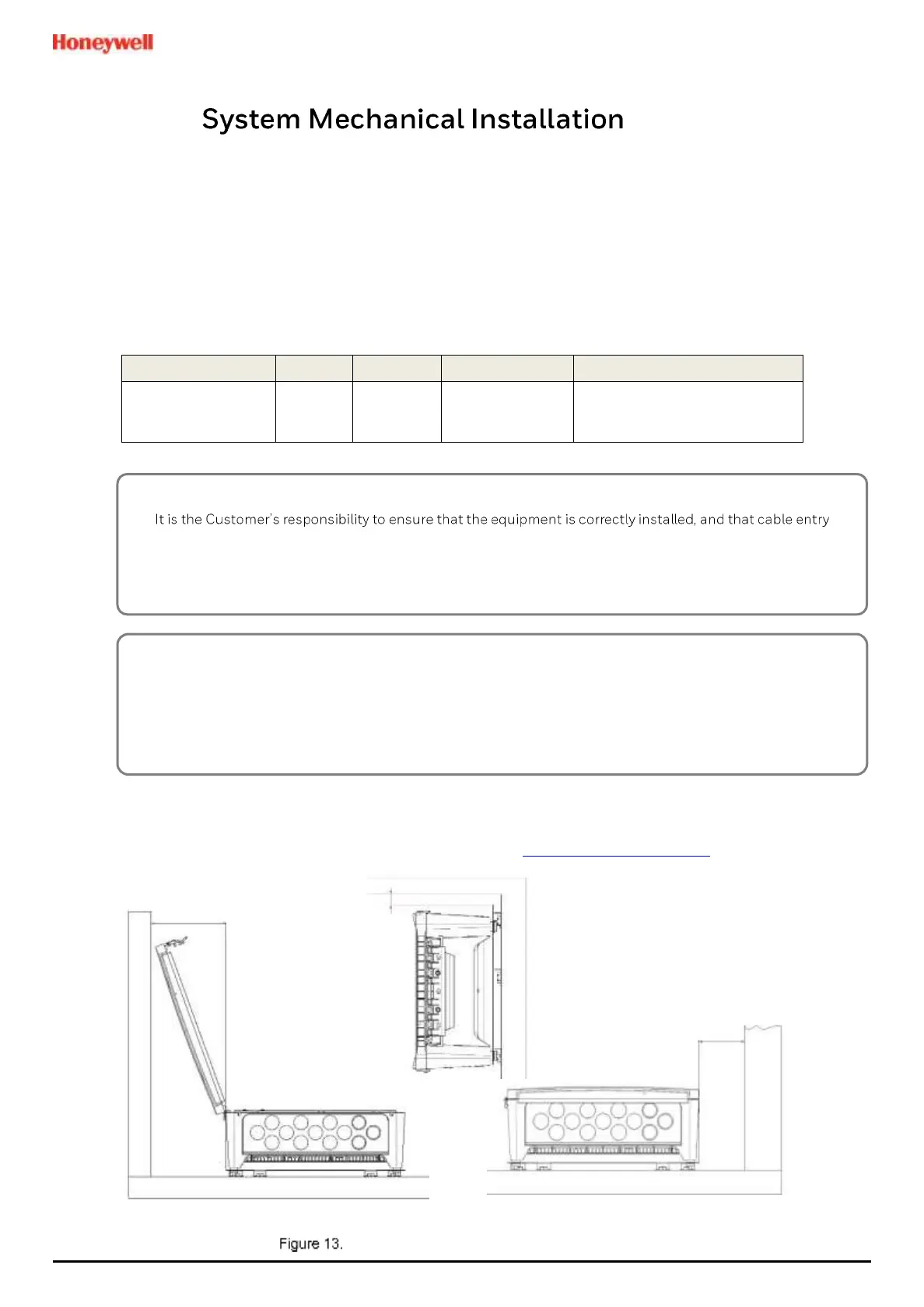
When choosing a location, it must be easily visible and accessible, with room to mount an external power isolator.
There must also be room to fully open the access door, which opens to the left, and room to easily access the door
locking handle and its securing screws, which are situated on the right. If using the optional expansion unit there
must be sufficient room between them to access the locking handle and its securing screws.
The units should be mounted so that the screen can be easily accessed and seen, but they should not obstruct
accesses, walkways or exits.
Protect the unit from heat sources, direct sunshine, rain, severe weather, steam or excess humidity and condensation.
4.1 Wall Mounting Requirements
For details and drawings refer to Honeywell Analytics website at www.honeywellanalytics.com.
Installation Clearance Measurements
CAUTION
glands or blanks of the appropriate IP rating are correctly used.
Failure to do so will invalidate the quoted IP / NEMA / Pollution ratings and may invalidate the warranty.
CAUTION
The units as supplied have two hex-socket securing screws in the access door handle, and these have to be
fully unscrewed prior to opening the handle. Failing to do so could cause irreparable damage to the housing.
The handle must be correctly locked and the screws must be correctly tightened when the unit is in normal
operation. Failing to fully secure the enclosure is unsafe and will invalidate product certification.

 Loading...


